$GYDQW
&RQWUROOHU8VHU¶V*XLGH
$SSHQGL[$ +DUGZDUH0RGXOHV
A-6 3BSE 002 415R701 Rev A
$ &,56&&RPPXQLFDWLRQ,QWHUIDFH
7HFKQLFDO'DWD
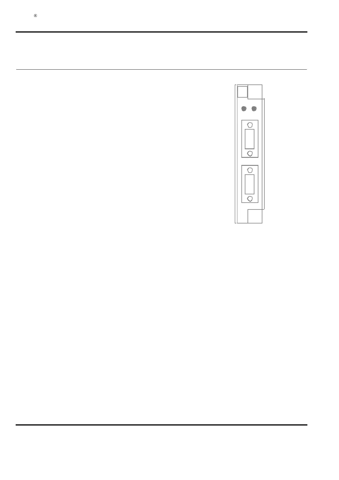
,QGLFDWRUV
LED R (green) on module front. Indicates module running normally.
LED F, Fault (red) on module front.
-XPSHUV
The board contains one jumper for special purposes.
In normal operation, always keep jumper S1 in position 3 - 4 (“parking place”).
The component and position indications are found on the printed circuit board.
&RQQHFWRUV
Serial channels 1 and 2 connectors (X4 and X5):
- Connector type Nine-pole male DSUB (DE9P)
- Placement On module front
- Pin designation See Table A-2 below.
• Two RS-232-C communication interface
• Modem support.
'HVFULSWLRQ
CI531 is a submodule destined to the Submodule Carrier SC510 and SC520
The two RS-232-C communication interfaces are generally used in the following
applications: Printer, EXCOM, MasterView 320. See the controller documentation.
The communication channels support communication speeds up to 19.2 kbaud
which is the limit set by the system software.
Both channels run at this speed simultaneously.
The maximum communication distance without modem is 15 m.
The modem signals which are supported are found in Table A-2 below.
Communication pins are short-circuit proof.
in Advant Controller 450 and Processor Module PM150 in Advant Controller 410.
X4
X5
FR
ABB
CI
531
)U RQ WYL HZ