Advant
®
Controller 450 User’s Guide
Chapter 2 Installation
2-76 3BSE 002 415R701 Rev A
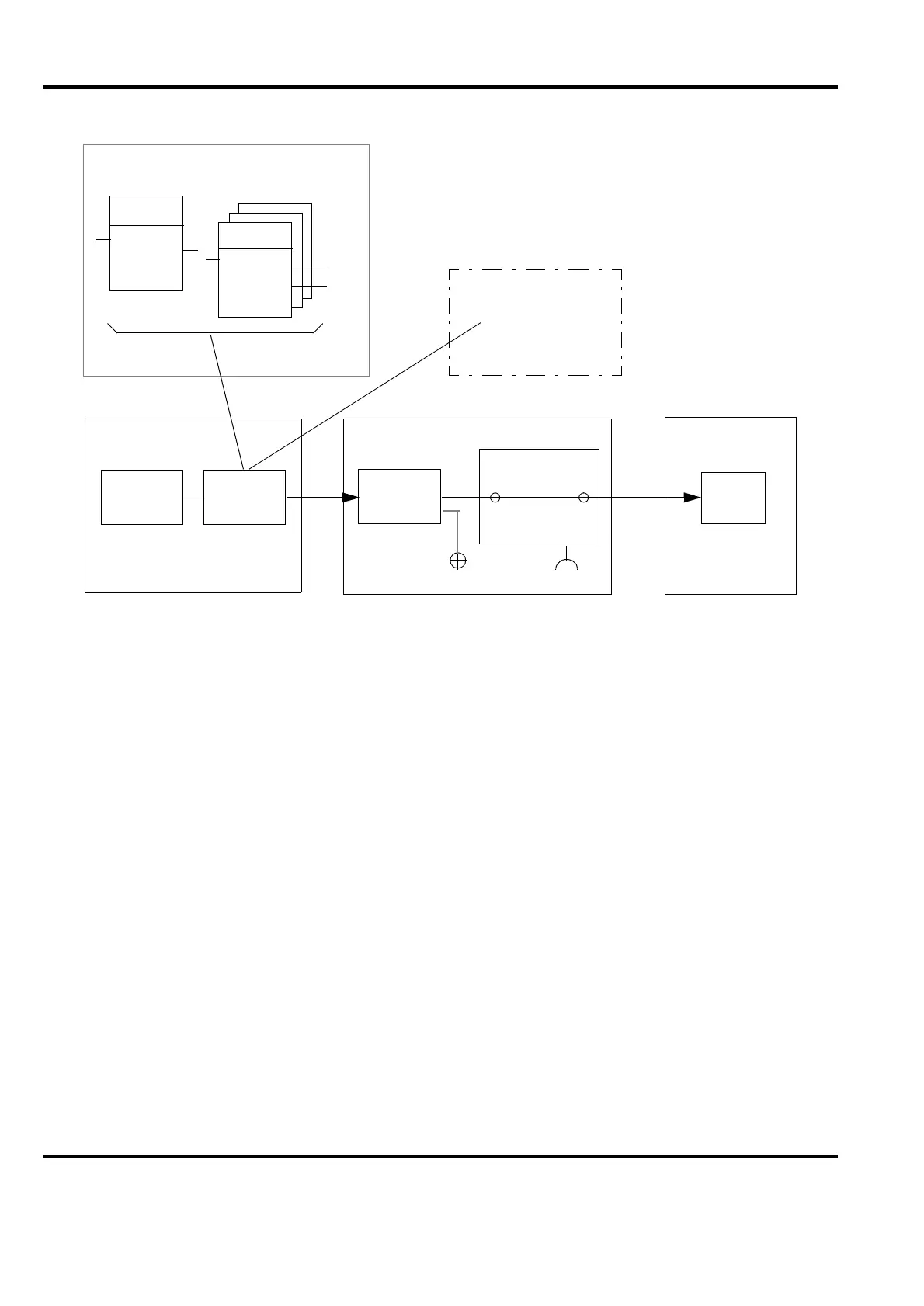
• Digital Output Signals
Figure 2-29 shows typical digital output channels and where you can test the signals.
Digital output signals in a specific plant are shown in the connection diagrams for the
plant.
Proceed as follows to check digital channels:
– Use the blocking command (BL) to block any PC programs already entered.
– Ensure that the data base connections for the output signals concerned are correct.
– Use the command MDB on the engineering unit to present the element in the data
base, set the VALUE and check that the corresponding output shows this value.
Then measure the value on the screw terminal block of the corresponding connection
unit end and, if practical, at the process as well.
– Check that the corresponding yellow LED on the digital output board concerned
illuminates.
When you are checking analog output signals, use a multimeter to test that an output signal is
obtained over the complete signal range.
Figure 2-29. Principal Block Diagram of S100 I/O Output Channel, Test Points
ProcessS100 I/O hw interfaceAC 450 sw interface
Connection
unit
Output
board
Process
object
Data basePC program
X90
Board
Signal
Engineering station
DB elements
VALUE
ERR
NAME
TYPE
ERR
Operator station
- Object display
- Trend curve
DO ch.