EasyManua.ls Logo

ABB Advant Controller 450 User Manual

ABB Advant Controller 450
564 pages
To Next Page IconTo Next Page
To Previous Page IconTo Previous Page
Page #342 background imageLoading...
Page #342 background image
Advant
®
Controller 450 User’s Guide
Chapter 4 Runtime Operation
4-20 3BSE 002 415R701 Rev A
4.1.9.2 Data Area for PC Programs
Each PC program is provided with a local data area for storage of variable values.
4.1.9.3 PC Program
You can divide a control task into a number of functional sections. The division is performed
primarily in accordance with the functional structure of the control task and can also be in
accordance with the requirement of different cycle times in the process. A PC program can
accordingly be divided into function modules and several execution units, which in turn consist
of PC elements.
Each execution unit can be given its own periodicity and its own execution conditions for
connection and disconnection.
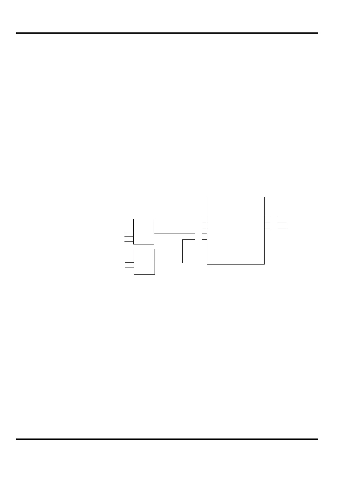
PC elements are the smallest “building blocks” in a PC program. They are described in detail in
the manual PC Elements. As an example, Figure 4-12 shows the graphical symbol for the PC
element FUNG-1V, a function generator. The figure also gives a rough outline of the supporting
elements for the break-points of the desired function (curve).
Figure 4-13 shows the desired application function.
Figure 4-12. Example of PC Element: FUNG-1V
FUNG-1V
(C1)
X
BAL
BALREF
XTAB
YTAB
Y
ERR
BALREFO
REG-G
REG-G
1
2
3
4
5
10
11
12

Table of Contents

Other manuals for ABB Advant Controller 450

Question and Answer IconNeed help?

Do you have a question about the ABB Advant Controller 450 and is the answer not in the manual?

ABB Advant Controller 450 Specifications

General IconGeneral
Power Supply24 V DC
Communication PortsEthernet
Programming LanguagesIEC 61131-3
I/O ModulesDigital, Analog
CertificationsCE, UL

Summary

Chapter 1 Introduction

1.7 Product Overview

Describes the Advant Controller 450 system, its capabilities, architecture, and components.

1.7.5 Power Supply

Describes the various power supply alternatives, including AC/DC options and redundancy.

1.7.6 Process Interface

Explains how the controller interfaces with the process via S100, S400, and S800 I/O systems.

1.7.8 Process Control

Covers built-in control functions, application programming language (AMPL), and PC elements.

1.7.10 Availability and Security

Discusses system reliability, availability, security measures, and redundancy concepts.

Chapter 2 Installation

2.1 Site Planning Environment

Provides guidelines for planning the physical installation, including site selection and environmental factors.

2.2 Setup

Provides step-by-step instructions for setting up the Advant Controller 450 system.

2.3 Shut-down Procedures

Explains how to safely shut down the controller and associated I/O systems.

2.4 Start-up Procedures

Guides through the power-up sequence and initial configuration of the system.

2.5 Product Verification

Outlines steps to verify the product's functionality after installation.

Chapter 3 Configuration/Application Building

3.1 Design Considerations

Key factors to consider during configuration and application building, including hardware, software, and guidelines.

3.2 Technical Data Including Capacity & Performance

Provides detailed technical specifications for system components like CPU, Power Supply, and Communication.

Chapter 4 Runtime Operation

4.1 Product Operation

Describes how to operate the Advant Controller 450, including working modes and start modes.

Chapter 5 Maintenance

5.1 Preventive Maintenance

Describes routine maintenance, replacement, and installation procedures.

5.2 Preventive Maintenance

Covers routine maintenance, replacement, and installation procedures for operation.

5.4 Error Messages

Describes types of error messages (Halt Codes, System Messages) and their handling.

5.5 Fault Finding and User Repair

Provides guidance on diagnosing and repairing faults, including principles and procedures.

5.6 CPU Load Measurement

Explains how to investigate and optimize CPU load using the ANPER command.

5.7 Backup

Covers procedures for backing up system and application data.

Appendix A Hardware Modules

A.5 PM511V - Processor Module

Provides technical details for the PM511V processor module, including memory and features.

Appendix B RM500 Cabinet - Data Sheet

Appendix C Delivery Documentation

Appendix D Item Designations

Appendix E Current Consumption and Heat Dissipation

E.2 Calculation Algorithms and Forms with Technical Data

Provides formulas for calculating current consumption and heat dissipation.

Appendix F Load Calculation

F.1 Load Calculation Forms

Offers forms for calculating CPU load from S100/S800 inputs, outputs, and user-defined types.

Appendix G Memory Calculation

G.1 Form for Memory Calculation

Provides forms for estimating RAM requirements based on object types and functions.

Appendix H Halt Codes

H.1 Example of Halt Code Printout

Shows an example printout of halt codes obtained from the LSYSHI command.

H.2 List of Halt Codes and Corrective Actions

Lists typical halt codes and their corresponding corrective actions for troubleshooting.

Appendix I System Messages

I.3 List of System Messages and Corrective Actions

Lists important system messages and their corrective actions for user self-correction.

Appendix J Hexadecimal to Decimal Representation

Related product manuals