Advant
®
Controller 450 User’s Guide
Chapter 2 Installation
2-24 3BSE 002 415R701 Rev A
Not CE-marked Design
The description given under the heading General is adequate. The cable is mechanically
anchored to the horizontal mounting bar close to the bottom of the cabinet. Leave the cable
unstripped. Use a cable clamp to press the cable against the bar or adjacent cable if several
cables are pressed together.
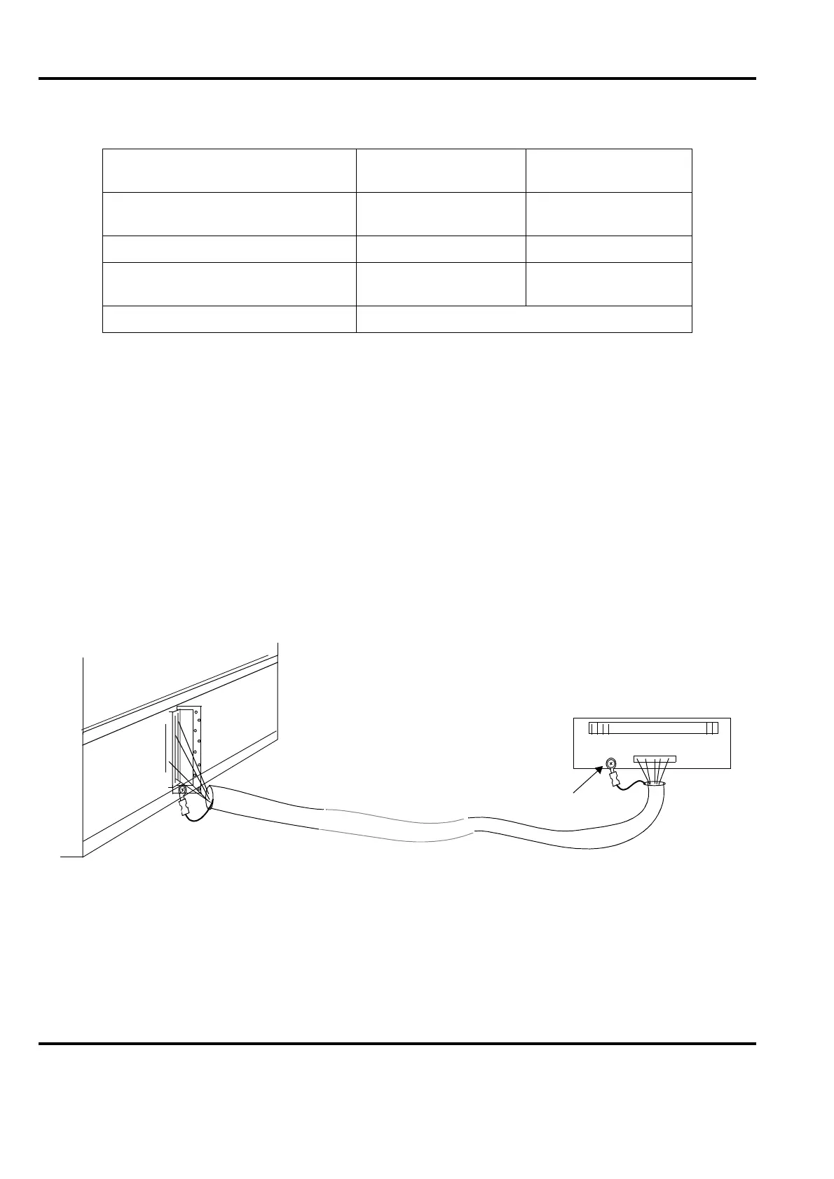
2.2.5.6 Grounding of “Internal” System Cable Shields, Connection Unit -- I/O Board
General
Use shielded cables to join distributed (
>
3 m) process connection units and I/O boards in a
subrack. Note that the internal cable must be routed separated from other cables.
Ground the shield in both ends. Use sheet cable lugs and self-tapping screws
ST3.5x9.5 (B6x9.5). See Figure 2-12.
LONWORKS Communication Twisted
pair
Yes, on one end Yes
PROFIBUS-DP Yes
V24/RS-232-C, for example for a
printer
Yes --
Bus Extension to S100 I/O Refer to Section 2.2.9, Bus Extension to S100 I/O
Figure 2-12. Grounding of Cable Shield, Connection Unit - I/O Board
Table 2-1. Methods of Handling Communication Cable Shields (Continued)
Type of Communication
Grounding of Shield
Directly
Grounding of Shield
via Capacitor
Process
connection
Connection
unit
I/O
subrack
Tinned
surface
Shielded cable
>
3 m (10 ft.)
I/O
board