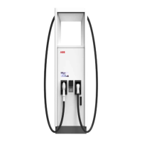
3.5.4 Charge post CP500 Generation 3, outside........................................................ 23
3.5.5 Charge post CP500 Generation 3, inside........................................................... 24
3.5.6 Overview of the cable glands of the charge post.............................................25
3.6 External residual-current device...........................................................................................25
3.7 Options......................................................................................................................................26
3.7.1 Tilt sensors...............................................................................................................26
4 Pre-installation.................................................................................. 27
4.1 Pre-installation procedure (site planning)..........................................................................27
4.2 Prepare the site........................................................................................................................27
4.3 Make sure that the floor space for the EVSE and the airflow around the EVSE is
correct........................................................................................................................................28
4.4 Prepare the foundation.......................................................................................................... 28
4.4.1 Prepare the foundation - general procedure.....................................................28
4.4.2 Prepare a prefab concrete foundation for the power cabinet...................... 28
4.4.3 Prepare a custom foundation for the power cabinet......................................29
4.4.4 Prepare a prefab concrete foundation for the charge post...........................30
4.4.5 Prepare a custom foundation for the charge post..........................................30
5 Inspection and transport..................................................................32
5.1 Transport the EVSE to the site..............................................................................................32
5.2 Inspect the EVSE on delivery................................................................................................. 32
5.3 Do a check on the transport sensors...................................................................................32
5.4 Unpack the EVSE......................................................................................................................32
5.5 Transport the EVSE on the site.............................................................................................33
5.5.1 General transport procedure................................................................................33
5.5.2 Tilt the charge post to the vertical position......................................................33
5.5.3 Move the cabinet with a forklift truck................................................................ 34
5.5.4 Hoist the cabinet.....................................................................................................35
5.6 Remove the cabinet from the pallet.................................................................................... 35
6 Installation..........................................................................................37
6.1 General installation procedure..............................................................................................37
6.2 Mechanical installation of the power cabinet....................................................................37
6.2.1 Install the power cabinet - general procedure.................................................. 37
6.2.2 Install the cabinet on the foundation................................................................. 38
6.2.3 Open the cable inlets .............................................................................................38
6.2.4 Guide the cables to the cabinet........................................................................... 39
6.2.5 Close the cable inlets ............................................................................................ 39
6.2.6 Install the front cover plate (concrete foundation)......................................... 39
6.3 Mechanical installation of the charge post........................................................................40
6.3.1 Install the charge post - general procedure......................................................40
6.3.2 Remove the cable gland plates.............................................................................41
Contents
4 9AKK107992A6488-EN | 004

 Loading...