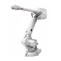
Refitting, upper arm
The procedure below details how to refit the upper arm.
NoteAction
Clean the joints that have been opened. See
Cut the paint or surface on the robot before re-
placing parts on page 219
1
Always use a new sealing when reas-
sembling!
Fit the new sealing, axis 2/3 onto the axis-3
gearbox and keep it in place by also fitting the
two guide pins, sealing axis 2/3 in two of the
attachment screw holes on the gearbox, see
figure to the right.
2
Art. no. is specified in Required equip-
ment on page 274.
xx0200000166
A Holes for the guide pins (sealing
axis 2/3).
B Holes for the upper arm attach-
ment screws (33 pcs).
C Holes for the gearbox attach-
ment screws (not affected in this
instruction).
Art. no. is specified in Required equip-
ment on page 274.
Upper arm including wrist unit:
Fit the lifting eye, VLBG M12 to the attachment
hole, lifting eye on the wrist unit.
3
Shown in the figure Location of upper
arm on page 273.
Art. no. is specified in Required equip-
ment on page 274.
Upper arm including wrist unit:
Fit one of the pieces included in the lifting ac-
cessory, upper arm to the front attachment for
the lifting accessory on the upper arm.
4
Attachment points are shown in the
figure Location of upper arm on
page 273.
Note
The different attachment points, de-
pends on whether the wrist unit is
mounted or not!
Upper arm without wrist unit:
Fit the lifting accessory, upper arm to the both
attachments for the lifting accessory on the
upper arm.
Art. no. is specified in Required equip-
ment on page 274.
Fasten the lifting tool (chain) onto the lifting eye,
the lifting accessory and an overhead crane.
5
Continues on next page
278 Product manual - IRB 6640 Foundry Prime
3HAC040586-001 Revision: N
© Copyright 2011-2018 ABB. All rights reserved.
4 Repair
4.4.4 Replacement of upper arm
Continued

 Loading...


