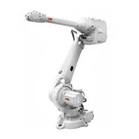
NoteAction
Figure showing the principal method!
xx0900000121
Cut the paint layer with a knife in the joint
between the cover and motor housing to
avoid that the paint cracks.
5
xx0600002874
• A: Attachment screws (4 pcs)
• B: Air hose (only Foundry Prime)
• C: Cover
• D: Motor axis 4
See the figure above!Cut the paint layer with a knife in the joint
between the motor and the upper arm
housing to avoid that the paint cracks.
6
See the figure above!Remove the cover for connector access on
top of the motor.
7
Keep the old cover with the air nipple fitted.8
Disconnect all connectors on motor axis 4.9
See section
• Manually releasing the brakes on
page 78
To release the brake, connect the 24 VDC
power supply.
Connect to connector R2.MP4:
• + = pin 2
• - = pin 5
CAUTION
Axis 4 might move when the brake is re-
leased and the balance of the axis is settled!
10
See the figure in:
• Location of motor axis 4 on page 362
Unscrew the motors attachment screws with
washers.
11
For article number see:
• Required equipment - tools etc. on
page 363
Fit guide pins in two of the holes.12
Continues on next page
Product manual - IRB 6640 Foundry Prime 365
3HAC040586-001 Revision: N
© Copyright 2011-2018 ABB. All rights reserved.
4 Repair
4.6.4 Replacing motor axis 4
Continued

 Loading...


