REV DESCRIPTION DATE DEPT./INIT.
- New document 2002-07-04 ATCF/FM/GF/RL
A 124,6 ±0,05 was 125 ±0,1. 2004-11-02 ATPA/FM/GF/LEN
B
View A added. Views in sheet 2 were in sheet 1. Holes Ø8.0 added.
Hole callout M16 adjusted. Hidden edges removed. Geometric
tolerances added. Dimensions adjusted.
2011-12-30 PA/FM/GF/ML
C
ABB AB
2012-01-13
Cont.sh./
No of sh.
SheetLang. Rev.
Project or order number :
Modify date :
Document number
Appr.
Prep.
Resp.dept
Product type designation :
Product information :
Product family :
2012-01-04 14:09:00
PFC200
661130 Bansp.mätare VPBT/HPBT
ABB AB
Håkan F Wintzell
2012-01-11Magnus X Lindström
1
1B
en
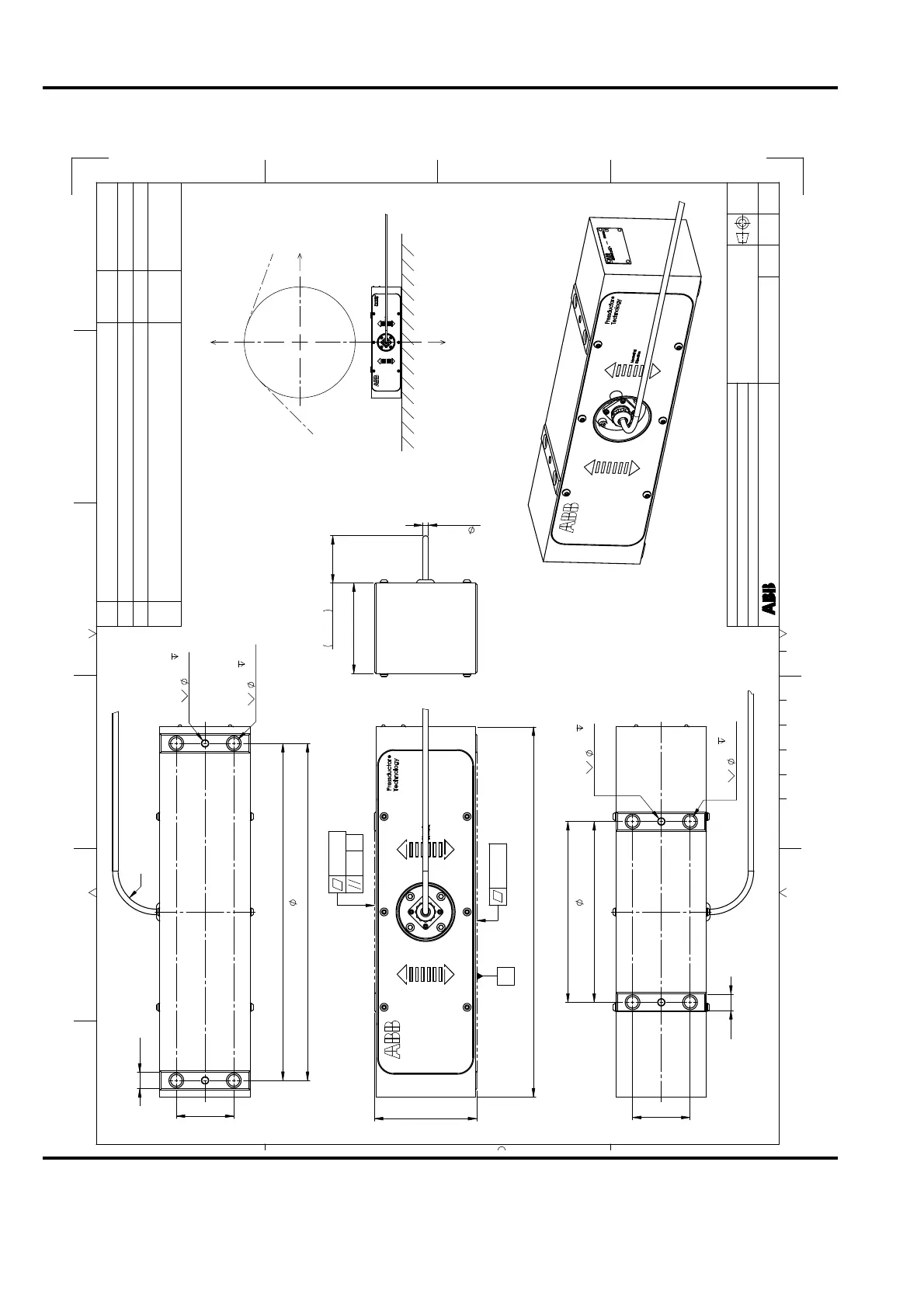
Lastcell PFCL 201CD
Load cell PFCL 201CD
Dimension drawing
3BSE029522D0001
PA
PA
PA
PA/FM/GF
FM/GF
FM/GF
Document status:
Approved
Customer reference :
/
/
/
= Force component (not measured).
F
v
= Measured component.
R
F
F
v
F
R
(
F
R
)
450
124,6 ±0,05
0,1 CZ
0,1 CZ
0,2 A
A
110
min 58
6,7
70 ±0,4
18 X 90°
4 x M16 25
9 X 90°
2 x Ø8.0 H8 10
220 ±0,2
(holes 8)
220 ±0,4
(holes M16)
20
410 ±0,4
(holes M16)
410 ±0,2
(holes 8)
70 ±0,4
18 X 90°
4 x M16 25
9 X 90°
2 x Ø8.0 H8 10
min R50
20