Tension Electronics PFEA111/112, User Manual
Section B.4 Installation Requirements
3BSE029380R0101 Rev C B-3
B.4 Installation Requirements
To achieve the specified accuracy, the best possible reliability and long-term stability, install the
load cells in accordance with the requirements below.
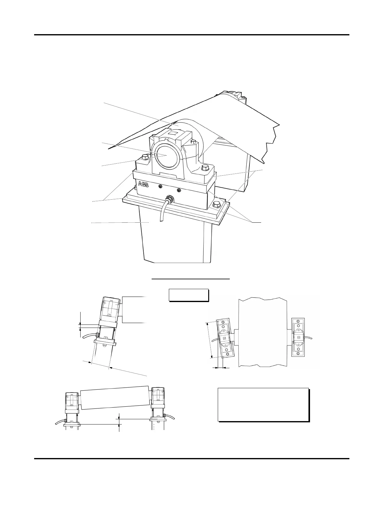
Figure B-1. Installation Requirements
Dynamically balanced
Self aligning bearings
Allow axial expansion
Mounting surface
must be flat within
Stable foundation
Correct torque for delivered screws intended
Shims may be placed
between the upper adapter
plate and the bearing housing
b)
Follow the manufacturer´s recommendation
Web
and between the lower adapter
for other screws.
for the adapter plates is 24 Nm (18 ft.-lb).
If the measuring roll is driven,
always consult ABB to ensure
0.1 mm (0.004 in.)
Alignment of the load cells
Grade G-2.5 ISO 1940-1.
that fulfills at least
measuring roll
of disturbances.
a solution with minimised risk
the load cell.
immediately above or below
Shims must not be placed
plate and the foundation.
6
7
m
m
(
2
.
6
4
)
a) Max. 0.5 mm (0.02 in.)
b) Max. 1.0 mm (0.04 in.)
a)
c)
c) Max. 5 mm/m (0.06 in./ft.)
when using long rolls
and large temperature
changes are expected.
228
(8.98)
mm (inches)