Tension Electronics PFEA111/112, User Manual
Section A.2.1 Coordinate System
3BSE029380R0101 Rev C A-3
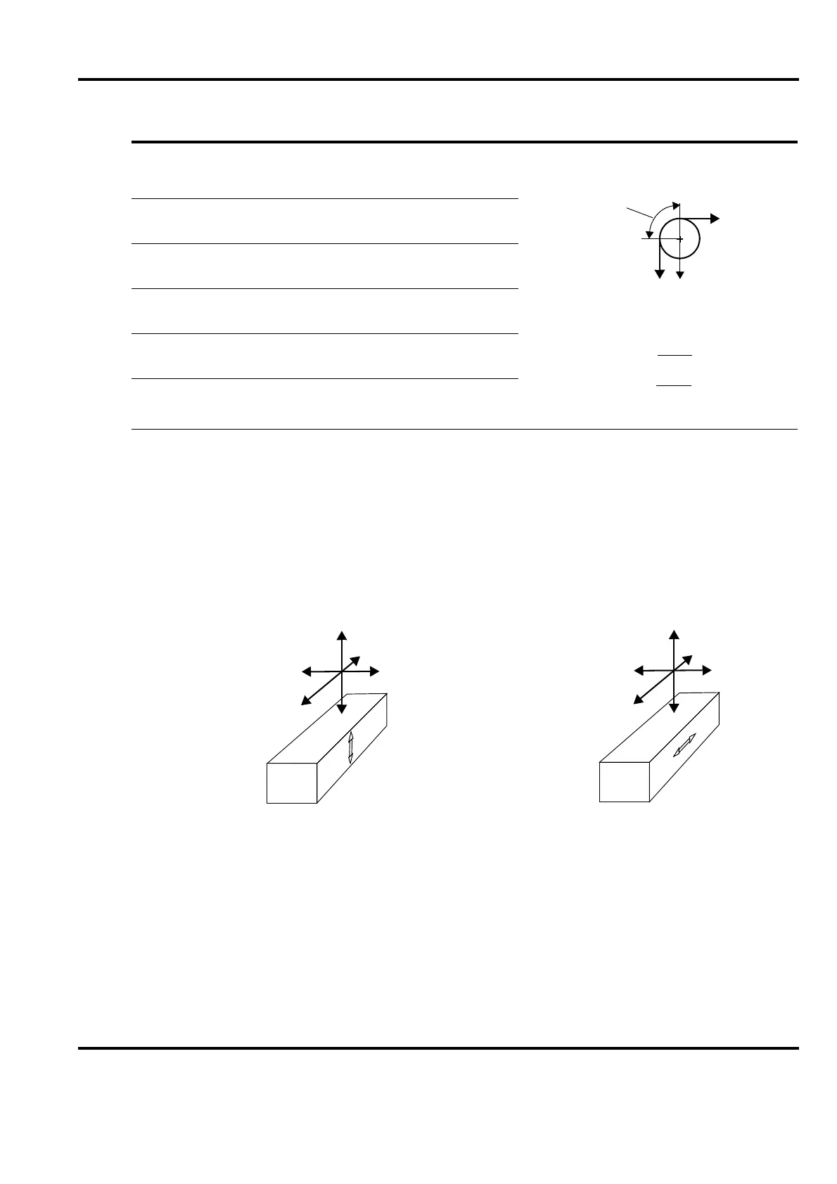
A.2.1 Coordinate System
A coordinate system is defined for the load cell. This is used in force calculations to derive force
components in the load cell principal directions.
Where direction designations R, V and A are recognized as suffixes for force components, F,
this represents the force component in the respective direction. The suffix R may be omitted,
when measuring direction is implied by the context.
Figure A-1. Coordinate System Defining Directions used in Force Calculations
T = Web tension.
Tare = Force of tare (weight of roll and bearing arrangement
mounted on the load cells)
F
R
= Measured force (force component of the web tension
in the measuring direction of the load cell).
F
RT
= Applied force component of tare in the measuring
direction of the load cell.
F
Rtot
= Total applied force in the measuring direction of the
load cell.
Wrap Gain = The ratio between web tension, T, and
measured force, F
R
.
Table A-1. Definitions
T
T
F
R
F
R
= T
Wrap angle
= = 1.00
Wrap gain =
Wrap gain
Wrap gain = 1.00
T
F
R
T
T
Example:
R
V
V
R
A
A
R = Measuring direction
V = Transverse direction
A = Axial direction
V
R
R
V
A
A