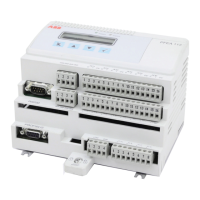
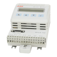
Tension Electronics PFEA111/112, User Manual
Chapter 3 Commissioning
3-4 3BSE029380R0101 Rev C
3.6 Step-by-step Commissioning Guide
Step Measurement See section
1 Check that the main supply voltage is switched off.
2 Check all cabling according to the cable diagrams. Appendix
B, C, D, E, F
or G
3 Check the supply voltage 3.7
DIN-rail mounted IP20-unit (unsealed)
Nominal 24 V DC, Working range 18 - 36 V DC, X1:1-2
Wall mounted IP65-unit (NEMA 4)
85 - 264 V AC (100 V - 15% to 240 V + 10%), 45-65 Hz, X9:1-2
Nominal 24 V DC, Working range 18 - 36 V DC, X1:1-2
4 Perform basic settings (if necessary) 3.7
5 Perform setup:
Fast setup 3.8
Complete setup 3.11
6 Check load cell signal polarity 3.9
7 Check load cell function 3.10
 Loading...
