Tension Electronics PFEA111/112, User Manual
Section 3.13.5 Handling of Measurement Data through Profibus
3BSE029380R0101 Rev C 3-31
3.13.5.4 Input Buffer, Communication Block from PFEA112 to PLC
This section specifies measurement values and Boolean values in the input buffer
communication block.
Data:
Value 1, Web tension
Step response time (filtering) equal to the setting for voltage output, 16-bit, 2-complement
representation (Integer 16)
Value 2, Web tension
Step response time (filtering) equal to the setting for current output, 16-bit, 2-complement
representation (Integer 16)
Boolean in:
The error or warning is active when the corresponding bit is set to “1”.
Bit No. 0: Flash memory error
Bit No. 1: EEPROM error
Bit No. 2: Supply error
Bit No. 3: Load cell excitation error
Bit No. 4: Synchronization problem
3.13.5.5 Output Buffer, Communication Block from PLC to PFEA112
This section specifies Boolean values in the output buffer communication block.
Bit No. 0: Zero set. Zero set is performed when the bit is changed from “0” to “1”.
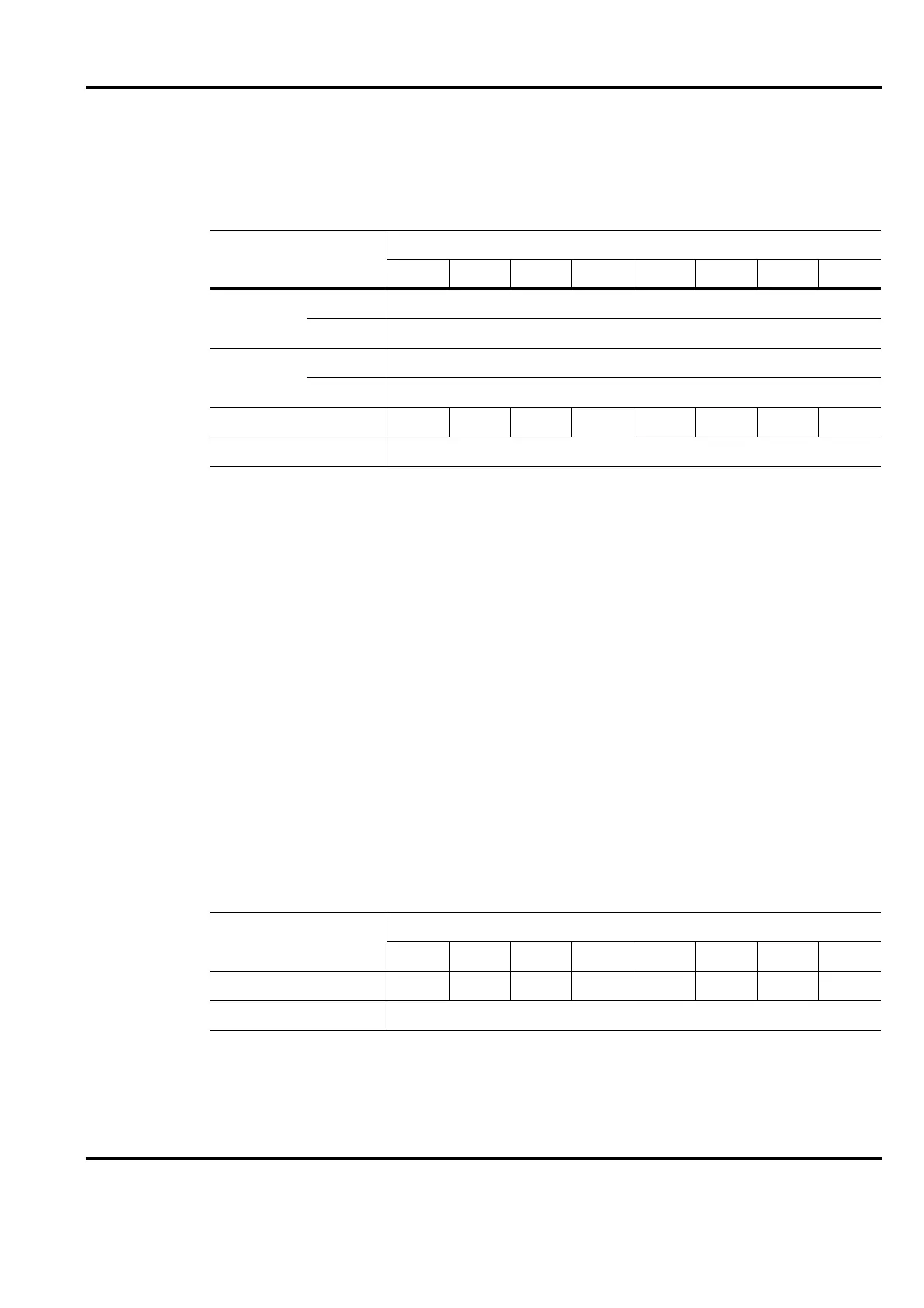
Data Byte No.
Bit No.
76543210
Value 1
01 MSB
02 LSB
Value 2
03 MSB
04 LSB
Boolean in 05 No. 7 No. 6 No. 5 No. 4 No. 3 No. 2 No. 1 No. 0
06 Spare for future use
Data Byte No.
Bit No.
76543210
Boolean out 01 No. 7 No. 6 No. 5 No. 4 No. 3 No. 2 No. 1 No. 0
02 Spare for future use