Tension Electronics PFEA111/112, User Manual
Section 2.5 Installing MNS Select Floor Cabinet
3BSE029380R0101 Rev C 2-9
2.5 Installing MNS Select Floor Cabinet
2.5.1 Mounting Cabinets Together
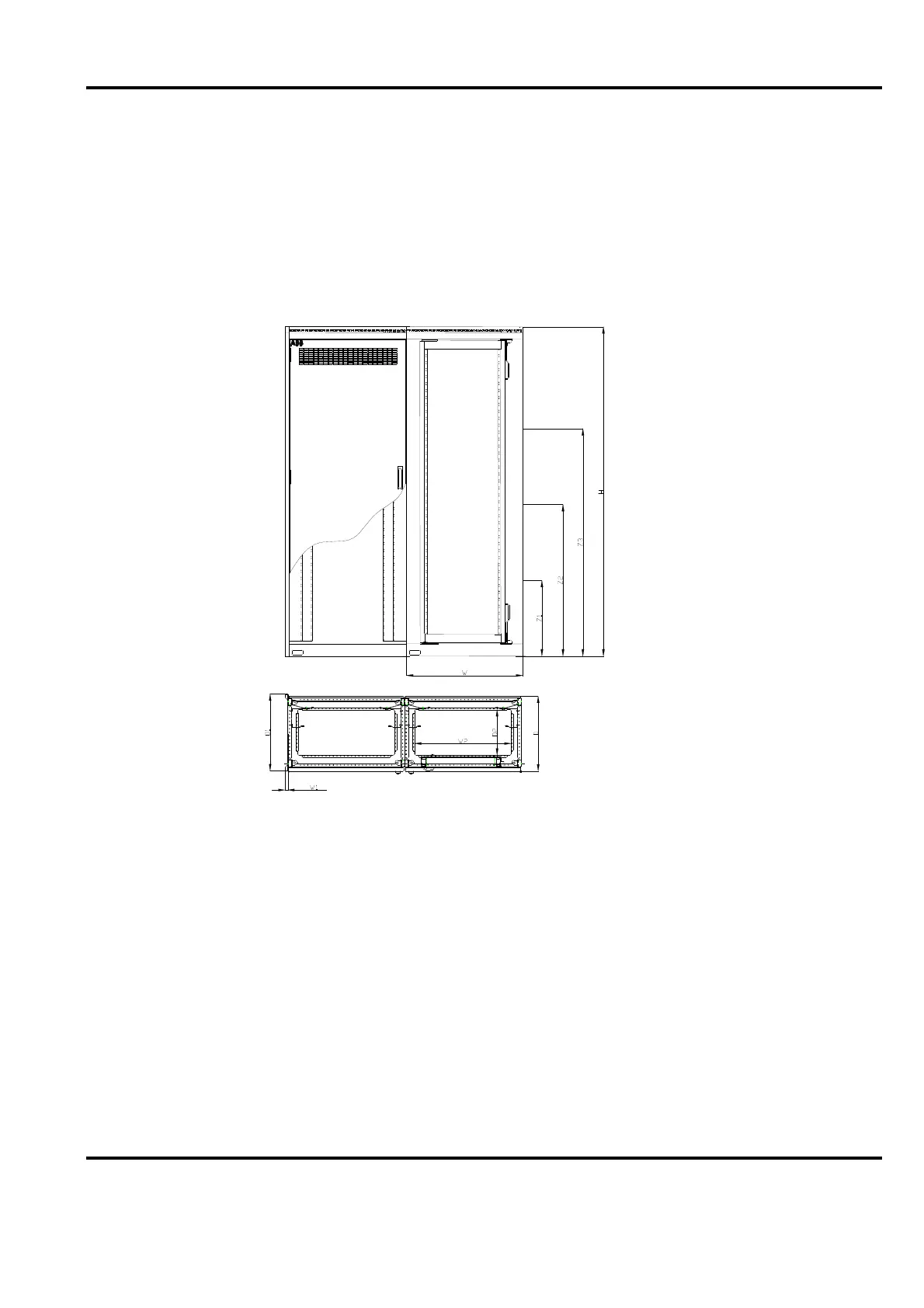
If cabinets are to be mounted to each other use the included screw/bolt kit. The four M8 screws,
with washers and nuts, in the angle hinges and six M6 screws at about Z1=500, Z2=1000,
Z3=1500 mm height from the floor, see Figure 2-9. Tighten the M8 screws to 20 Nm maximum
and the M6 screws to 10 Nm maximum.
Figure 2-9. Mounting Cabinets together - Screw Position
2.5.2 Mounting Cabinets to the Floor
When fixing the cabinet to the floor use four or six M12 screws where Figure 2-10 indicates,
one at each corner in the first left hand cabinet in a row of cabinets and screw the following
cabinets with two screws each at the right hand side. The bottom angle hinges features holes,
14 mm (0.6”) in diameter. These holes permit you to adjust the cabinet location after holes are
drilled in the floor. If drilling is necessary, make sure that no dust or other foreign matter enters
the equipment in the cabinet. Please notice the minimum distances from cabinet to walls and
ceiling. Use washers between the floor and the cabinet bottom to level the cabinet floor into a
horizontal position.