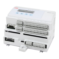
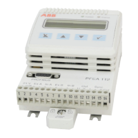
Tension Electronics PFEA111/112, User Manual
Section 6.7 Fault Symptoms and Measures
3BSE029380R0101 Rev C 6-5
6.7 Fault Symptoms and Measures
General remark:
If the free (unscreened) cable length exceeds 0.1 m (4 in.) the individual pairs of power and
signal conductors must be twisted.
Free length exceeding 0.1 m can cause unstable zero point or incorrect absolute measurement
value.
Table 6-1. Fault Symptoms and Measures
Fault symptom Measures
Noisy signals - Check that cable shields are connected to earth
according to cable diagram.
- Proximity to noisy cables can cause interference
problems.
Unstable zero point - Check that cable screens are not connected in
both ends.
- Check that cable between load cell and electronic
has diagonal pairs, one pair for signal circuit and
one par for excitation circuit, see Figure 2-2.
- Check, if a junction box is installed, that load cell
signal and load cell excitation between junction
box and electronics are routed in separate cables.
- Check, if two or more IP 20 units are mounted
close to each other in the same cabinet, that they
are synchronized (cable for synchronizing the
units, see cable diagram and Section 2.4.1.3
Synchronization).
Display and LED indictors are
not illuminated
If the Operator panel display is not illuminated and
the “Power” and “Status” indications on the
Operator Panel are “OFF”, check the following:
- Check that the cables are correctly connected to
the electronics power supply.
- Check that the power supply connected to the
electronics is correct.
- Check that the power switch is “ON” (inside the
IP 65-version (NEMA 4) enclosure).
- Further tests are described in Section 6.8.1.3
Supply Error.
 Loading...
