Tension Electronics PFEA111/112, User Manual
Section 2.4.1 Selecting and Routing the Cabling
3BSE029380R0101 Rev C 2-3
• The maximum permitted cable resistance in the excitation circuit is shown in Table 2-1.
Before commissioning, check cable resistance in the load cell excitation circuit.
• Solid conductors should not be connected to terminals. Pins should not be crimped to
stranded cores.
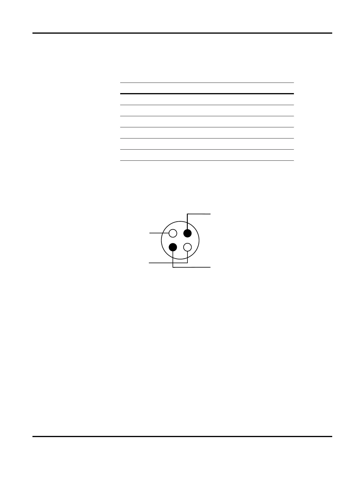
• The cable from the load cell must be a robust four core cable, see Figure 2-2.
Diagonal pairs must be
used for the signal circuits and excitation circuits.
Figure 2-2. Core Arrangement in Load Cell Cable
• Between the junction box and the tension electronics, signal and excitation must be routed
in separate cables. For example: a 2 × 2.5 mm
2
cable for the excitation and a shielded
2 × 2 × 0.5 mm
2
cable with twisted pair cores for the load cell signals.
• Cable for synchronization of two of more tension electronics must be screened or a twisted
pair.
• The signal cable between the tension electronics and instruments, or process equipment,
must be a screened 0.5 mm
2
cable.
• Cable screens must be connected to the copper earth bar. The screen connection maximum
length is 50 mm.
• The protective earth conductor of the incoming mains supply must be connected to the
copper earth bar in the cubicle.
Table 2-1. Maximum Permitted Cable Resistance
Load cell Max. permitted cable resistance
PFCL 301E 5
PFTL 301E 5
PFRL 101 5
PFTL 101 5
PFCL201 5
PFTL 201 5
Signal
Load cell excitation
A
B
D
C