Tension Electronics PFEA111/112, User Manual
Chapter 2 Installation
2-6 3BSE029380R0101 Rev C
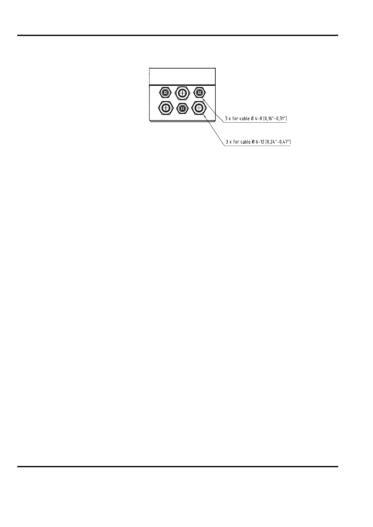
Figure 2-5. Cable Glands PFEA 112
Connect the cables to terminals according cable diagrams in Appendix (B, C, D, E, F or G)
depending on installed load cell type.
NOTE
Do not connect solid conductors to terminals. Do not crimp pins to stranded
cores.
NOTE
The incoming mains voltage must be provided with fuses and a means of
disconnection outside the tension electronics.