The type B curve is described as:
2.0
480
0.055
Vpickup < -V
32 0.5
Vpickup
TD
t
×
= +
× -
<
æ ö
ç ÷
è ø
EQUATION1608 V1 EN (Equation 34)
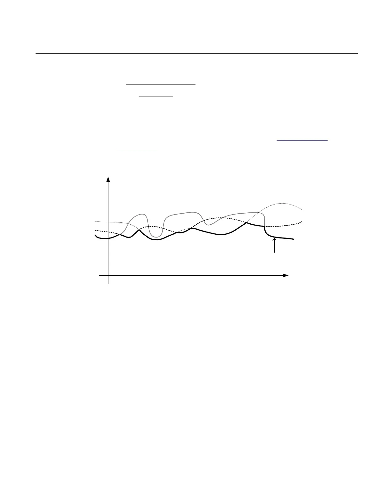
The lowest voltage is always used for the inverse time delay integration. The details of the
different inverse time characteristics are shown in section 19.3 "Inverse time
characteristics".
Figure 69: Voltage used for the inverse time characteristic integration
Voltage
IDMT Voltage
Time
VL1
VL2
VL3
ANSI12000186-1-en.vsd
Trip signal issuing requires that the undervoltage condition continues for at least the user
set time delay. This time delay is set by the parameter t1 and t2 for definite time mode (DT)
and by some special voltage level dependent time curves for the inverse time mode
(TUV). If the pickup condition, with respect to the measured voltage ceases during the
delay time, the corresponding pickup output is reset.
7.1.7.3 Blocking
It is possible to block Two step undervoltage protection (UV2PTUV ,27) partially or
completely, by binary input signals or by parameter settings, where:
BLOCK:
blocks all outputs
BLK1: blocks all pickup and trip outputs related to step 1
BLK2: blocks all pickup and trip outputs related to step 2
1MRK 511 287-UUS A Section 7
Voltage protection
171
Technical manual

 Loading...


