FOCUS 200 PLUS Installation and Setup Guide
12-4
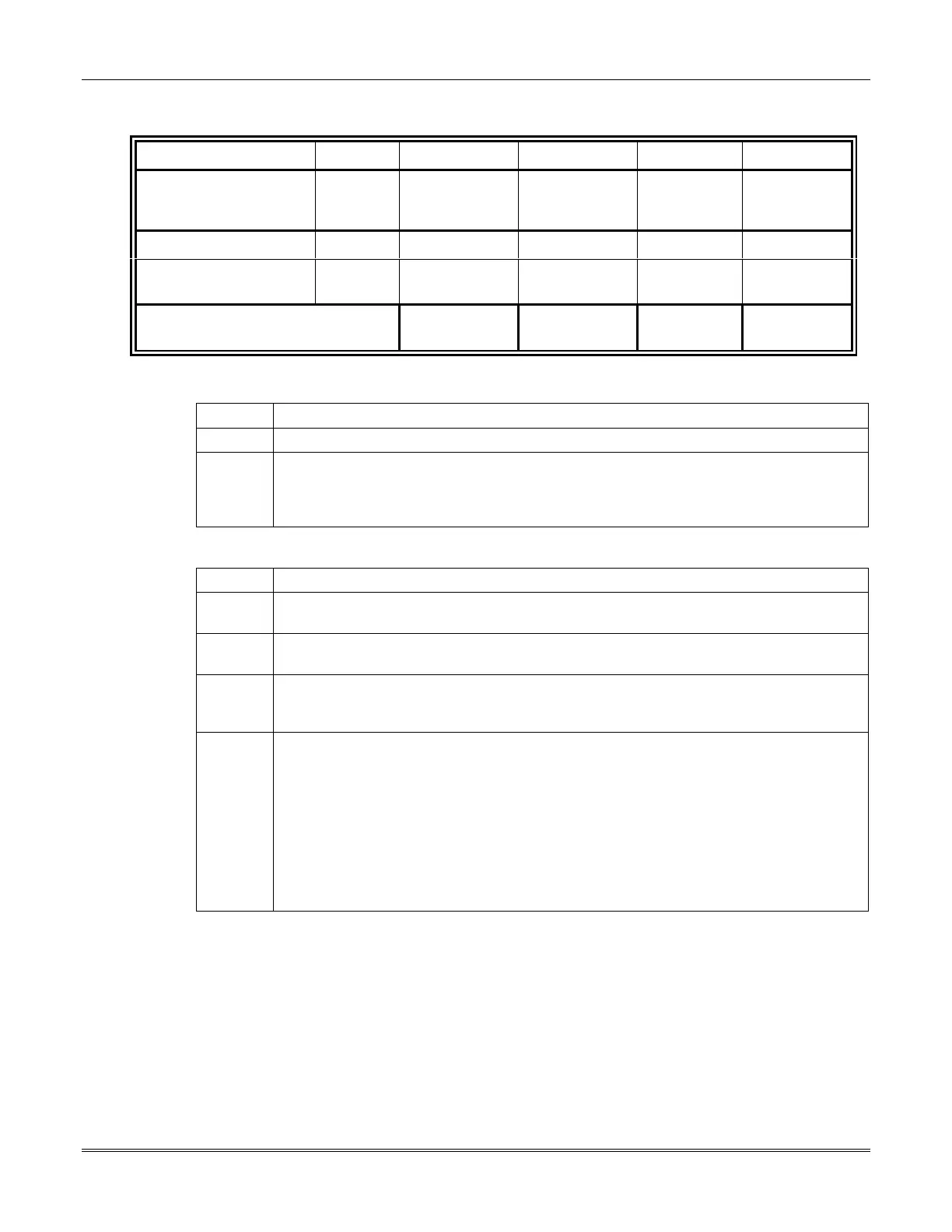
Table 3: RF Gateway & RF Receiver Standby and Alarm Loads
Gateway Unit No. 7 (Max. 72 Points)
A B AxB C AxC
Device Quantity
Standby
Current (mA)
Total
Standby
Current (mA)
Alarm
Current
(mA)
Total Alarm
Current
(mA)
RF Gateway
150 50 5050
RF Receiver
(maximum 2)
60 60
Total Gateway & Receiver
Standby and Alarm Current
Standby Alarm
To calculate the standby and alarm loads for each gateway, perform the following steps:
Step Action
1 Make a copy of each table for each gateway on the system.
2 Fill in Tables 1, 2, and 3 to calculate the standby and alarm current loads for each
gateway. Use Table 1 for PID Gateways, Table 2 for SIM Gateways, and Table 3 for RF
Gateways. These totals will be used to determine the gateway trunk cable lengths and
the size of the system’s backup battery.
Drawing Load Diagrams for the RS-485 Buses
Step Action
1 Using the Load Diagrams shown in
Figures 12-1
and
12-2
as an example, make a similar
diagram showing each device (gateway, operating panel, etc.) along each RS-485 bus.
2 Estimate the cable distance in feet from the control unit to the first device on the bus,
and also the distance between devices. Then, mark the distances on the Load Diagram.
3
Enter the total alarm load that each operating panel and gateway present to the RS-485
bus. Enter this data in the appropriate boxes that represent the operating panels (use
65mA for each) and gateways (total from the previous tables).
4
Record, on the Load Diagram, the current that will flow through each section of the RS-
485 bus using the following information:
a.
The current through the first section of the bus is the sum of all loads presented by
the operating panels and gateways.
b.
The current through the second section is the sum of all loads (obtained in item (a)
above) minus the load for the first gateway, operating panel, or other device on the
bus.
c.
The current through the third section will be the sum of all loads minus the loads for
the first and second devices on the bus.
 Loading...


