ix
List of Figures
•••••••••••••••••••••••••••••••••••••••••••••••••
Figure 2-1: Installing Cabinet Lock ................................................................................................................................. 2-2
Figure 2-2: Cabinet Attack Resistance Considerations.................................................................................................... 2-3
Figure 2-3: Cabinet Door Tamper Wiring........................................................................................................................ 2-3
Figure 2-4: Mounting the PC Board................................................................................................................................. 2-4
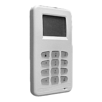
Figure 3-1: Details of the Operating Panel Circuit Board............................................................................................... 3-2
Figure 4-1: 2-Wire Smoke Detector Connected to Point 1 (can also be connected to Point 2, Terminals 27 and 28)..... 4-3
Figure 4-2: 4-Wire Smoke Detector Connections Points 1-8............................................................................................. 4-4
Figure 4-3: Style "D" Configuration on Points 3 and 4.................................................................................................... 4-4
Figure 5-1: PID Gateway Module..................................................................................................................................... 5-4
Figure 5-2: PID Wiring Connections to System-Powered Sensors................................................................................. 5-10
Figure 5-3a: Basic Sensor Connections to PID................................................................................................................. 5-11
Figure 5-3b: Basic Sensor Connections to PID................................................................................................................. 5-11
Figure 5-4: Connections of BA Sensors with Field Wiring Terminals to PID............................................................... 5-12
Figure 5-5: Using a PID to Turn On a PA400W Sounder............................................................................................. 5-12
Figure 5-6: SIM Gateway Module .................................................................................................................................. 5-14
Figure 5-7: SIM Wiring to System-Powered and Nonpowered Sensors........................................................................ 5-18
Figure 5-8: Connection for a Gateway Loop Powered SIM Sensor................................................................................ 5-19
Figure 5-9: SIM Wiring to a Horn and Strobe............................................................................................................... 5-19
Figure 5-10: SIM Wiring to a Sensor ............................................................................................................................... 5-20
Figure 5-11: SIM Connections to a Vault Vibration Sensor............................................................................................ 5-20
Figure 5-12: SIM Connections to a 4-Wire/2-Wire Adapter............................................................................................ 5-21
Figure 5-13: Loop Interface Module ................................................................................................................................. 5-22
Figure 5-14: Loop Interface Module Wiring to Powered Sensor...................................................................................... 5-23
Figure 5-15: Loop Interface Module Wiring to Lacing/Foil and Non-powered Sensor.................................................. 5-23
Figure 5-16: RF Gateway Wiring Connections................................................................................................................. 5-24
Figure 5-17: RF Receiver DIP Switch Settings ................................................................................................................ 5-26
Figure 6-1: External Sounder Connections to the Bell Outputs ...................................................................................... 6-6
Figure 6-2: External Sounder Connections to the Auxiliary Relay ................................................................................. 6-7
Figure 7-1: Installing the 472402A Backup Dialer.......................................................................................................... 7-3
Figure 8-1: AC Communicator Module Wiring................................................................................................................ 8-2
Figure 8-2: AC Communicator Module Wiring Using AC Telephone Lines.................................................................... 8-3
Figure 8-3: AC Communicator Module Wiring Using DVACS or RS232 Port............................................................... 8-3
Figure 8-4: AC Communicator Module Wiring Using DC Telephone Lines ................................................................... 8-4
Figure 9-1: Configuration of the 7720P to the J5 Output Triggers................................................................................. 9-4
Figure 9-2: Configuration of the 7830R to the J5 Output Triggers................................................................................. 9-5
Figure 9-3: Configuration of the 7835C to the J5 Output Triggers................................................................................. 9-5
Figure 9-4: Configuration of the 7920SE to the J5 Output Triggers............................................................................... 9-6
Figure 10-1: Access Control Interface Unit (ACIU).......................................................................................................... 10-3
Figure 10-2: Typical Installation Using Card Reader or Keyreader............................................................................. 10-10
Figure 10-3: Typical Installation Using a Keylok.......................................................................................................... 10-10
Figure 10-4: Modifying ACIU for Operation with Dorado 7401 or 7901 Card Reader................................................ 10-11
Figure 10-5: Wiring Connections for a Manual Access Pushbutton or Exit Pushbutton.............................................. 10-12
Figure 11-1: Printer Interface Unit................................................................................................................................... 11-2
Figure 12-1: Load Diagram for RS-485 Bus.................................................................................................................... 12-5
Figure 12-2: Load Diagram for RS-485 Bus with Power Supply.................................................................................... 12-6
Figure 12-3: Determining the Voltage Drop on the RS-485 Bus...................................................................................... 12-7
Figure 12-4: Determining Maximum Length of Quad Trunk for PID Gateway (no horn/strobes)................................ 12-8
Figure 12-5: Determining the Maximum Length of Quad Trunk for SIM/PID Gateway with Horn/Strobes.............. 12-9
Figure 19-1: Operating Panel........................................................................................................................................... 19-1
Summary of Connections.......................................................................................................Inside Back Cover
 Loading...