Installation and Configuration Ensemble HLe
2.2.2. DC Brush Motor Connections
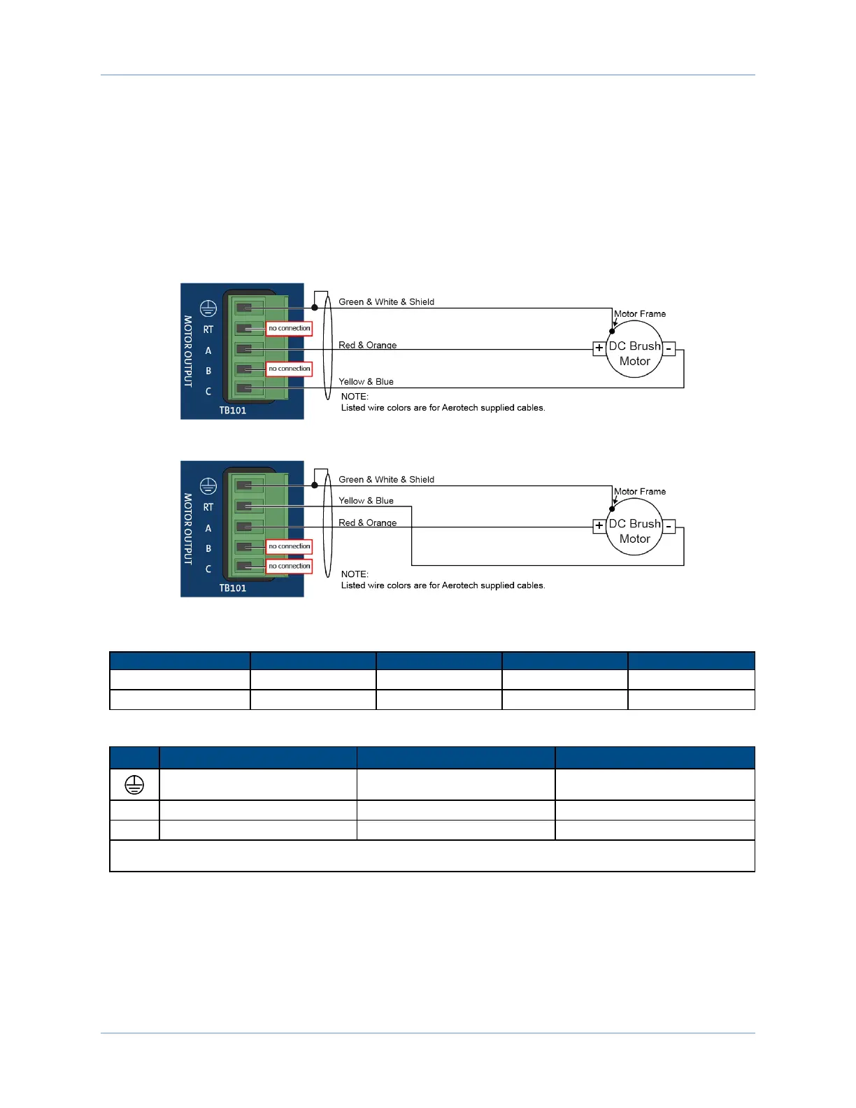
The configuration shown in Figure 2-7 is an example of a typical DC brush motor connection. Refer to
Section 2.2.2.1. for information on motor phasing.
Connecting the motor between amplifier terminals A and C gives two times the nominal voltage output.
Connect between the A and RTterminals if this voltage is not required or to reduce heat generation in the
amplifier. In this case, Resistance, Inductance, and BackEmf motor parameters must be doubled before
using in the current loop calculator or linear amplifier protection parameters.
Figure 2-7: DC Brush Motor Configuration
Figure 2-8: DC Brush Motor Configuration with RTConnection
Table 2-6: DCBrush Voltage Output Configuration
Connection HLe 20-40 HLe 10-40 HLe 10-60 HLe 10-80
A-C 80V 80V 120V 160V
A-RT 40V 40V 60V 80V
Table 2-7: Wire Colors for Aerotech Supplied Cables (DCBrush)
Pin
Wire Color Set 1
(1)
Wire Color Set 2 Wire Color Set 3
Green & White & Shield
(2)
Green/Yellow & Shield Green/Yellow & Shield
A Red & Orange Red Red & Orange
C Yellow & Blue Black Yellow & Blue
(1) Wire Color Set #1 is the typical Aerotech wire set used by Aerotech.
(2) “&” (Red & Orange) indicates two wires; “/ ” (Green/White) indicates a single wire
www.aerotech.com Chapter 2 31