Installation and Configuration Ensemble HLe
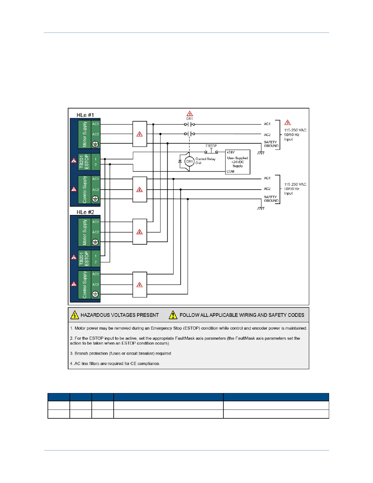
2.4.1. Typical ESTOP Interface
The user can connect an external emergency stop relay circuit to the Ensemble HLe’s motor power supply
input. This will remove power to the motor while maintaining control power, as shown in the Figure 2-25.
The external relay must be sized based on the number of the Ensemble HLes connected and the peak
current rating of each drive.
Figure 2-25: Typical Emergency Stop Circuit
Table 2-21: Typical ESTOPRelay Ratings
Axes AC1 AC3 Aerotech P/N Third Party P/N
1 32 16 ECW1018 Sprecher &Schuh CA7-16C-xx-xxx
2 to 5 85 43 ECW1019 Sprecher &Schuh CA7-43C-xx-xxx
www.aerotech.com Chapter 2 51