92 Chapter 4 www.aerotech.com
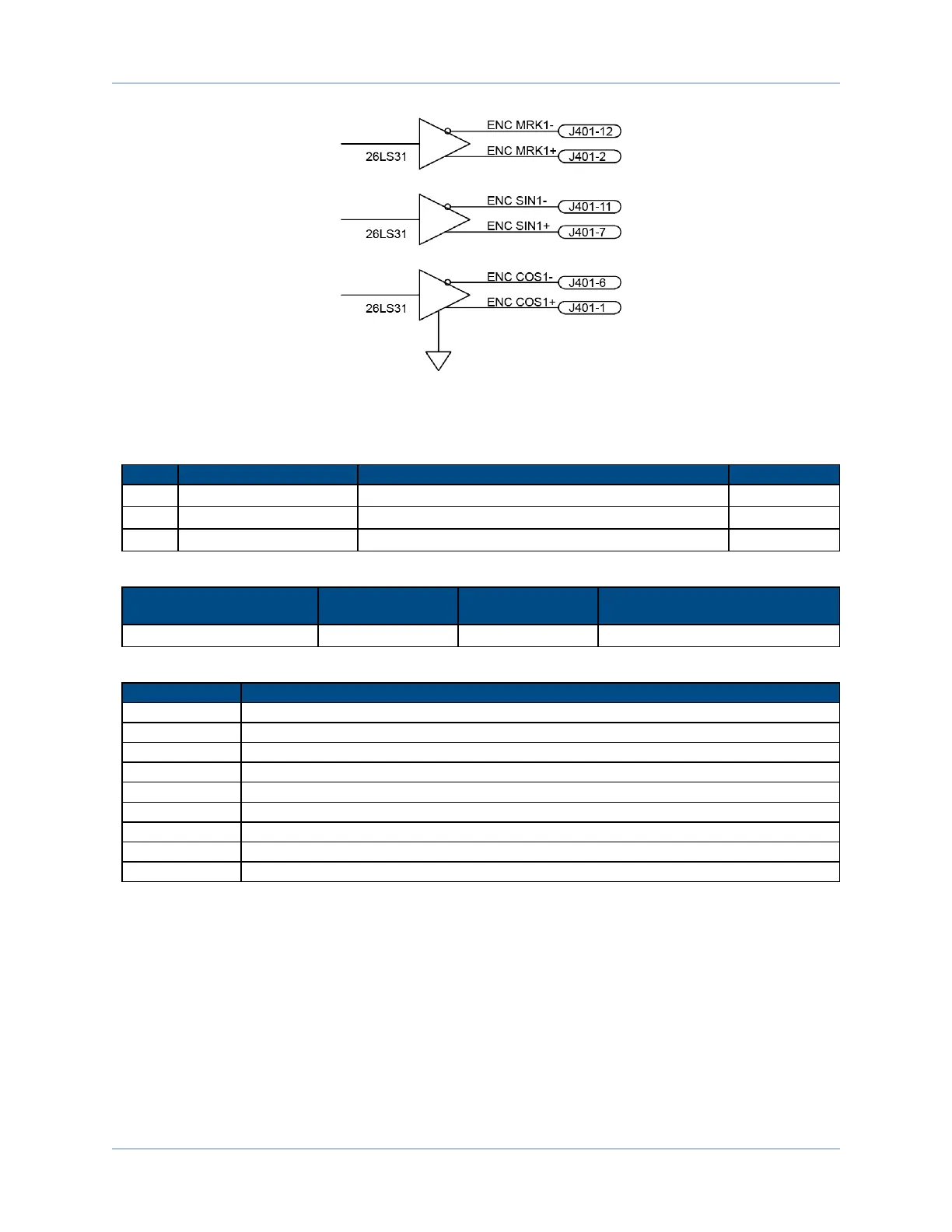
Figure 4-4: Encoder Emulation Outputs
The external power connector (J403) is a factory-select configuration and is not available on all drives.
Table 4-4: External Power Pin Assignment (J403)
Pin# Label Description In/Out/Bi
1 +12V +12 Volts DC Input
2 -12V -12 Volts DC Input
3 COM Signal Common N/A
Table 4-5: External Power Mating Connector
Description Aerotech P/N Phoenix P/N
Wire Size:
AWG [mm
2
]
3-Pin Terminal Block ECK01449 1881338 0.5 - 0.080 [20-28]
Table 4-6: Resolver Test Points
Test Point # Description
TP4 Signal Common
TP10 Sine Input Channel 1
TP11 Cosine Input Channel 1
TOP Reference Signal Channel 1
TP13 Resolver Channel 1 Error
TP20 Sine Input Channel 2
TP21 Cosine Input Channel 2
TP22 Reference Signal Channel 2
TP23 Resolver Channel 2 Error
Ensemble HLe -RDP Expansion Board