-IO Expansion Board Ensemble HLe
3.1. Relay Connector (TB301)
The relay can be used to automatically control a fail-safe brake on a vertical axis. It can also be used as a
general purpose relay. The normally-open relay contacts are accessible through TB301 and the Motor
Feedback connector. The normally-closed relay contact is only accessible through TB301 (see Figure 3-3).
The Motor Feedback connector allows the brake wires to be included in the motor feedback cable and
eliminate the need for a separate brake cable.
The brake output can be software configured; refer to the EnsembleHelp file for more information (see topics
for the EnableBrakeControl parameter and the BRAKE command).
When TB301 is used to power the mechanical brake control relay, the solid state brake control relay (TB202)
should not be used.
The user must verify that the application will be within the specifications of the Brake/Relay contacts.
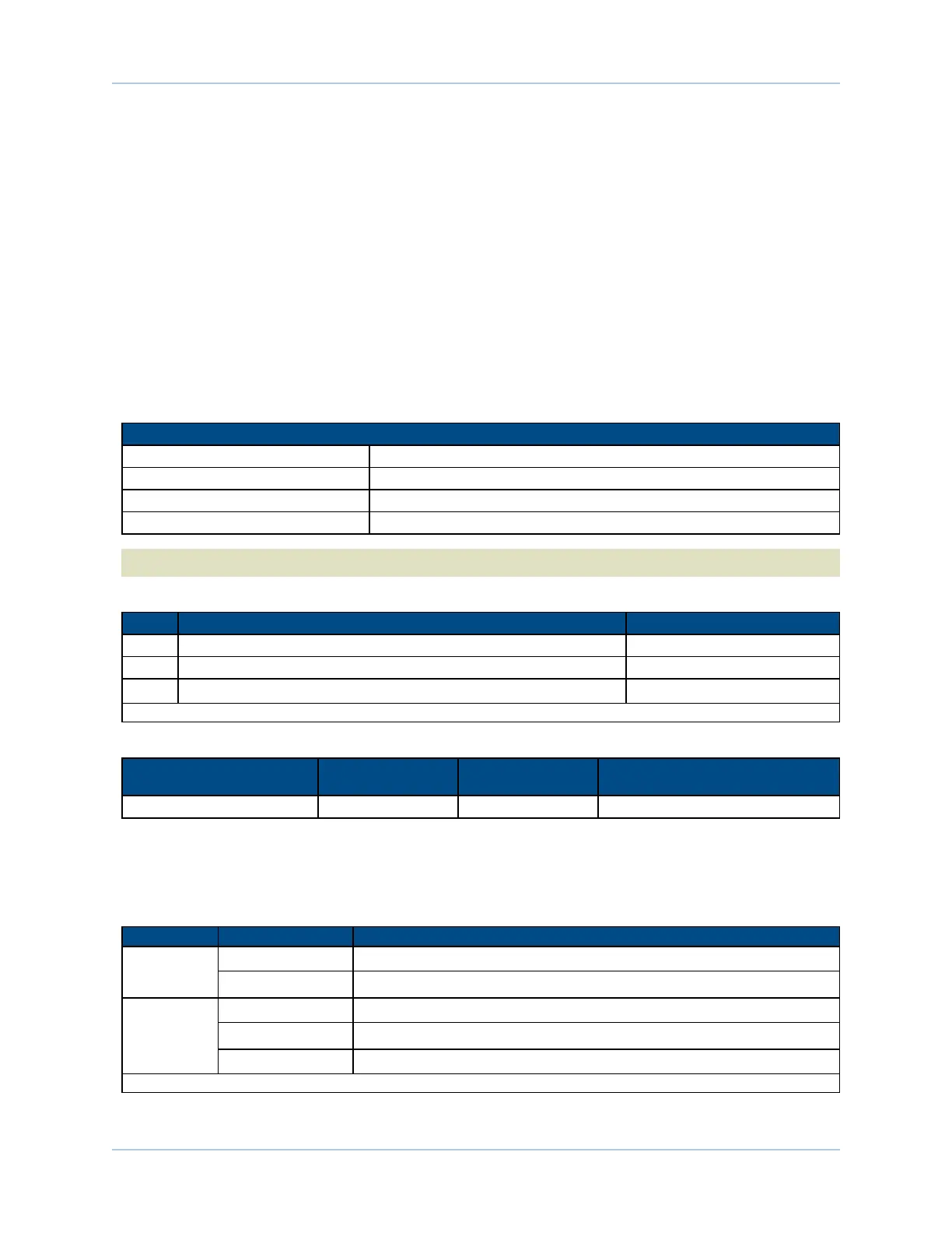
Table 3-3: Voltage and Current Specifications (TB301)
Relay K1 Contact Ratings
Maximum Switched Voltage 150 VDC, 125 VAC
Maximum Switched Current 1A
Maximum Carrying Current 1A
Maximum Switched Power 30 W (DC), 60 VA (AC)
N O T E : Do not exceed Maximum Current or Maximum Power specifications.
Table 3-4: Brake / Mechanical Relay Connector Pinout (TB301)
Pin# Description In/Out/Bi
1 Brake Relay Output Normally Closed Contact Output
2 Brake Relay Output Common Contact Output
3
Brake Relay Output Normally Open Contact
(1)
Output
(1) For JP3 jumper configuration, refer to Table 1-1.
Table 3-5: Mating Connector Part Numbers for the Relay Connector (TB301)
Description Aerotech P/N Phoenix P/N
Wire Size:
AWG [mm
2
]
3-Pin Terminal Block ECK01449 1881338 0.5 - 0.080 [20-28]
The configuration of JP3 (Table 3-6) allows either the Brake + or the Brake - output to be switched by the
relay and connected at the Motor Feedback connector or for the brake to be connected at TB301. Refer to
Section . for more information.
Table 3-6: -IO Expansion Board Brake Jumper Configuration
Jumper Setting Description
JP2
1-2 PSO Output Active High, Low Z during reset
2-3
(1)
PSO Output Active Low, High Z during reset
JP3
1-2, 3-4 Switch Brake +
5-6, 7-8
(1)
Switch Brake -
1-3 Relay Only
(1) default
www.aerotech.com Chapter 3 71