52 Chapter 2 www.aerotech.com
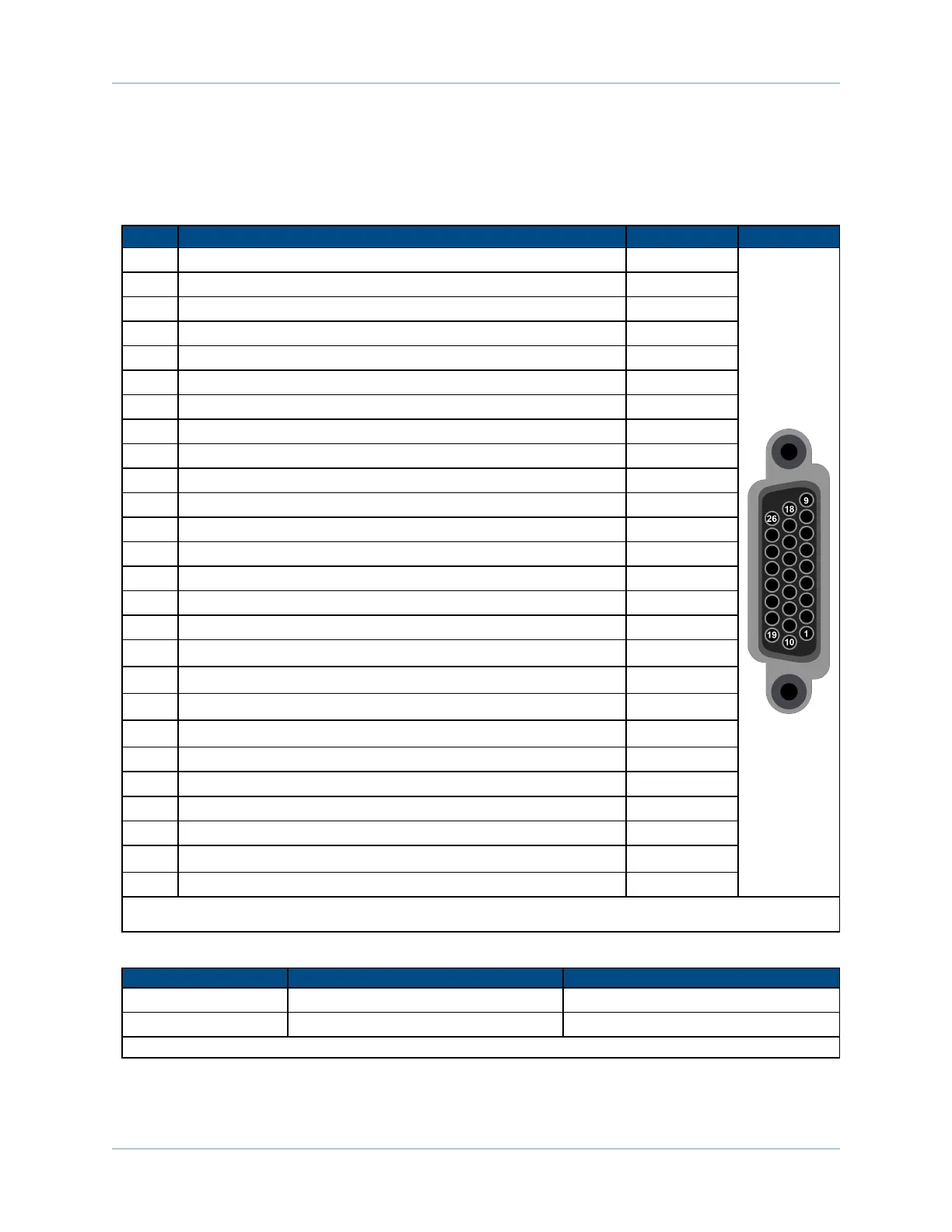
2.5. Auxiliary I/O Connector (J205)
The Auxiliary I/O connector (J205) provides 1 analog and 6 digital inputs, 1 analog and 4 digital outputs, and
a secondary RS-422 line driver encoder input.
Table 2-22: Auxiliary I/O Connector Pinout (J205)
Pin# Description In/Out/Bi
Connector
1 Auxiliary Sine+ Bidirectional
2 Auxiliary Sine- Bidirectional
3 High-Speed Input 4 + user interrupt Input
4 High-Speed Input 4 - user interrupt Input
5 High-Speed Input 5 + user interrupt Input
6 High-Speed Input 5 - user interrupt Input
7 Digital Output 0 Output
8 Digital Output 1 Output
9 Digital Output 2 Output
10 Auxiliary Cosine+ Bidirectional
11 Auxiliary Cosine- Bidirectional
12 +5 Volt (500 mA max) Output
13 Analog Input 0 + (Differential) Input
14 Analog Input 0- (Differential) Input
15 Output Common -
16 Digital Output 3 Output
17
Digital Input 0 / CCW EOT Input
(1)
Input
18
Digital Input 1 / CW EOT Input
(1)
Input
19
Auxiliary Marker- / PSO output
(2)
Bidirectional
20
Auxiliary Marker+ / PSO output
(2)
Bidirectional
21 Common (+5 Volt User Supply, 500 mA max) -
22 Analog Output 0 Output
23 Analog Common -
24 Input Common -
25
Digital Input 2 / Home Input
(1)
Input
26 Digital Input 3 Input
(1) Software configured option
(2) For PSO, see Section 2.5.2.
Table 2-23: Mating Connector Part Numbers for the Auxiliary I/OConnector
Mating Connector Aerotech P/N Third Party P/N
Connector ECK01259 Kycon K86-AA-26P
Backshell ECK01022 Amphenol 17E-1725-2
NOTE:These items are provided as a set under the Aerotech P/N:MCK-26HDD.
Ensemble HLe Installation and Configuration