-IO Expansion Board Ensemble HLe
3.2. PSO Output Interface (TB302)
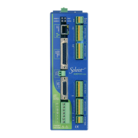
The output can be used to source or sink current (as shown in Figure 3-4 and Figure 3-5).
By default, JP2 is installed in the 2-3 position for normally open operation. If the PSO-NC option is ordered,
JP2 is installed in the 1-2 position giving normally-closed operation. This mode should be used with caution
since the Ensemble HLe cannot maintain the closed state when its AC mains power is turned off. The PSO-
NC (JP2 1-2 setting) should not be used when fail-safe operation is required. JP2 jumper settings are shown
in Table 3-9. For the JP2 jumper location, refer to Figure 3-1
TB302 provides an open-collector PSOoutput. Jumper JP2 defines the active state of the open-collector
output (defined in Table 3-7). Multiple opto-coupler options are available, depending on output speed,
voltage, and current requirements. An external power supply is required for the PSOOPTO1/2 options.
Table 3-7: PSO Output Interface Connector Pin Assignment (TB302)
Pin # Description In/Out/Bi
1 Reserved --
2 PSOOutput Output
3 Opto-Isolator Common Input
Table 3-8: Mating Connector Part Numbers for the PSO Output Connector (TB302)
Description Aerotech P/N Phoenix P/N
Wire Size:
AWG [mm
2
]
3-Pin Terminal Block ECK01449 1881338 0.5 - 0.080 [20-28]
Table 3-9: PSO Output Polarity Settings for JP2
PSO Output Polarity JP2 Setting
Normally Open 2-3 (Recommended)
Normally Closed 1-2
Table 3-10: PSOOutput Specifications
Description Specification
Maximum Voltage 24 V
Current 250 mA
Latency 120 ns
Maximum Frequency 5 MHz
Figure 3-4: PSO Output Sources Current Figure 3-5: PSOOutput Sinks Current
www.aerotech.com Chapter 3 73