20 Chapter 1 www.aerotech.com
1.2. Electrical Specifications
The safe operating range is load dependent.
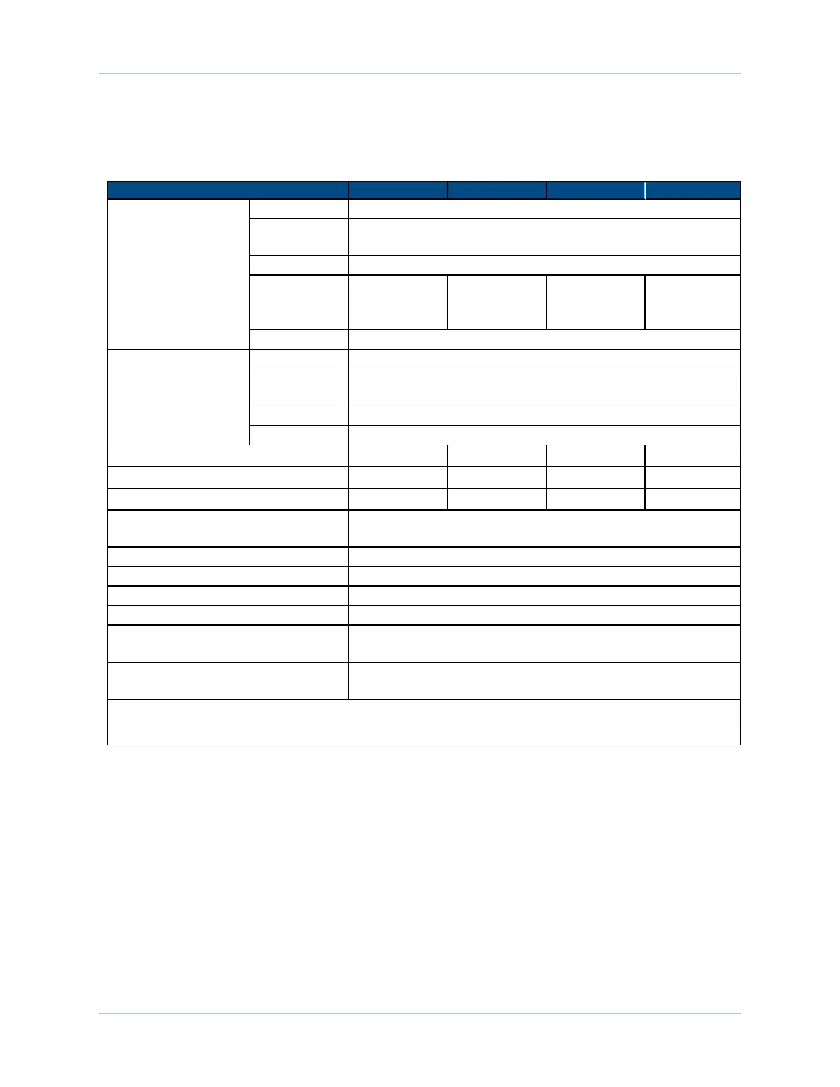
Table 1-6: Electrical Specifications
HLe 20-40 HLe 10-40 HLe 10-60 HLe 10-80
Motor Supply
Input Voltage 100, 115, 200, 230 VAC (model dependent)
Input
Frequency
50-60 Hz
Inrush Current 10, 11.5, 20, 23 A (model dependent)
Maximum
Continuous
Input Current
5.66 A
rms
2.83 A
rms
5.66 A
rms
5.66 A
rms
Input Current Refer to Section 1.2.1. System Power Requirements
Control Supply
Input Voltage 85-240 VAC
Input
Frequency
50-60 Hz
Inrush Current 16 A
Input Current .25 A max
Output Voltage
(1)
±36 V @ 20A ±38 V @ 10A ±58 V @ 10A ±78 V @ 10A
Peak Output Current
(2)
20 10 10 10
Continuous Output Current
(2)
10 5 5 5
Power Amplifier Bandwidth (selectable
via parameters)
2500 Hz maximum (software selectable)
Minimum Load Resistance 0.5 Ω
Output Impedance 0.2 Ω (each phase)
User Power Supply Output 5 VDC (@ 500 mA)
Modes of Operation Brushless; Brush; Stepper
Protective Features
Peak current limit; Over temperature;
RMScurrent limit; Dynamic power dissipation limit
Isolation
Optical and transformer isolation between control and power
stages.
(1) Load Dependent
(2) Peak and continuous output current is load dependent (the amplifier willlimit its output current based on velocity and motor
resistance).
Ensemble HLe Introduction