Installation and Configuration Ensemble HLe
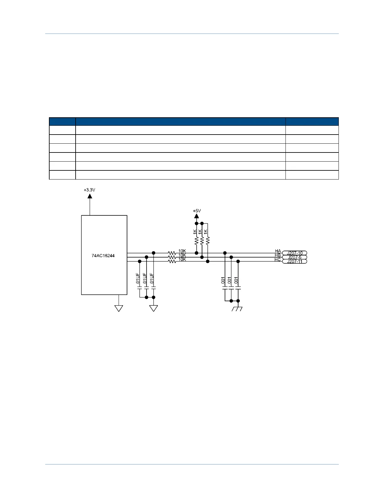
2.3.2. Hall-Effect Interface (J207)
The Hall-effect switch inputs are recommended for AC brushless motor commutation but not absolutely
required. The Hall-effect inputs accept 5-24 VDC level signals. Hall states (0,0,0) or (1,1,1) are invalid and
will generate a "Hall Fault" axis fault.
Refer to Section 2.2.1.1. for Hall-effect device phasing.
Table 2-14: Hall-Effect Feedback Pins on the Motor Feedback Connector (J207)
Pin# Description In/Out/Bi
1 Chassis Frame Ground N/A
3 +5V Power for Encoder (500 mAmax) Output
5 Hall-Effect Sensor B (brushless motors only) Input
10 Hall-Effect Sensor A (brushless motors only) Input
11 Hall-Effect Sensor C (brushless motors only) Input
21 Signal Common for Encoder N/A
Figure 2-18: Hall-Effect Inputs (J207)
www.aerotech.com Chapter 2 43