Installation and Configuration Ensemble HLe
2.5.3. Digital Outputs 0-3 (J205)
The digital outputs are optically-isolated and may be connected in sourcing or sinking configurations. The
digital outputs are designed to connect to other ground referenced circuits and are not intended to provide
high-voltage isolation.
The outputs are software-configurable and must be connected in either all sinking or all sourcing mode.
Figure 2-28 and Figure 2-29 illustrate how to connect to an output in current sourcing and current sinking
modes.
The opto-isolator's common connections can be directly connected to the drive's power supply; however,
doing so will effectively defeat the isolation and will reduce noise immunity.
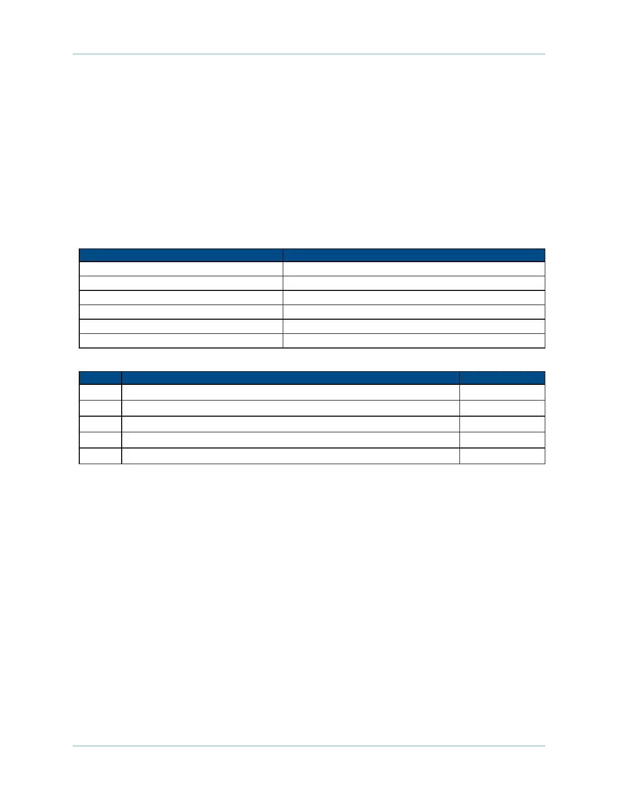
Table 2-28: Digital Output Specifications
Opto Device Specifications Value
Maximum Voltage 24 V maximum
Maximum Sink/Source Current 60 mA/channel @50°C
Output Saturation Voltage 2.75 V at maximum current
Output Resistance 33 Ω
Rise / Fall Time 250 usec (typical)
Reset State Output Off (High Impedance State)
Table 2-29: Port 0 Digital Output Pins on the Auxiliary I/O Connector (J205)
Pin# Description In/Out/Bi
7 Digital Output 0 Output
8 Digital Output 1 Output
9 Digital Output 2 Output
15 Output Common -
16 Digital Output 3 Output
www.aerotech.com Chapter 2 57