-IO Expansion Board Ensemble HLe
N O T E : Power supply connections must always be made to both the Output Common Plus (OP) and
OutputCommon Minus (OM) pins as shown in Figure 3-13 and Figure 3-14.
N O T E : Outputs must be connected as all sourcing or all sinking.
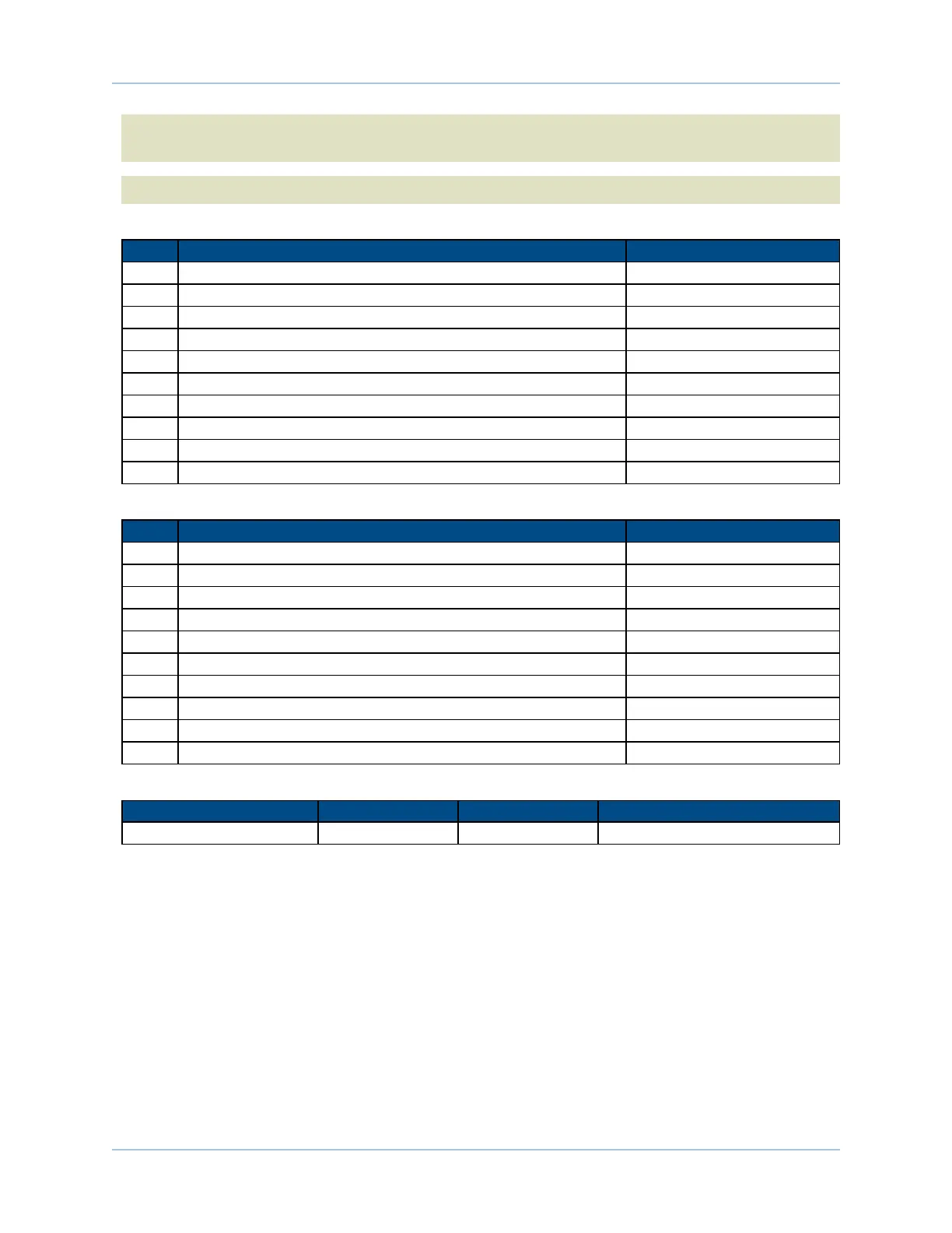
Table 3-25: Port 1 Opto Out Connector Pinout (TB307)
Pin# Description In/Out/Bi
1 Digital Output Common Plus Input
2 Digital Output Common Minus Input
3 Digital Output 0 (Optically-Isolated) Output
4 Digital Output 1 (Optically-Isolated) Output
5 Digital Output 2 (Optically-Isolated) Output
6 Digital Output 3 (Optically-Isolated) Output
7 Digital Output 4 (Optically-Isolated) Output
8 Digital Output 5 (Optically-Isolated) Output
9 Digital Output 6 (Optically-Isolated) Output
10 Digital Output 7 (Optically-Isolated) Output
Table 3-26: Port 2 Opto Out Connector Pinout (TB308)
Pin# Description In/Out/Bi
1 Digital Output Common Plus Input
2 Digital Output Common Minus Input
3 Digital Output 0 (Optically-Isolated) Output
4 Digital Output 1 (Optically-Isolated) Output
5 Digital Output 2 (Optically-Isolated) Output
6 Digital Output 3 (Optically-Isolated) Output
7 Digital Output 4 (Optically-Isolated) Output
8 Digital Output 5 (Optically-Isolated) Output
9 Digital Output 6 (Optically-Isolated) Output
10 Digital Output 7 (Optically-Isolated) Output
Table 3-27: Mating Connector Part Numbers for the Opto Out Connectors (TB307/TB308)
Aerotech P/N Phoenix P/N
Wire Size: mm
2
[AWG]
10-Pin Terminal Block ECK01294 1881406 0.5-0.080 [20-28]
www.aerotech.com Chapter 3 83