28 Chapter 2 www.aerotech.com
2.2.1. Brushless Motor Connections
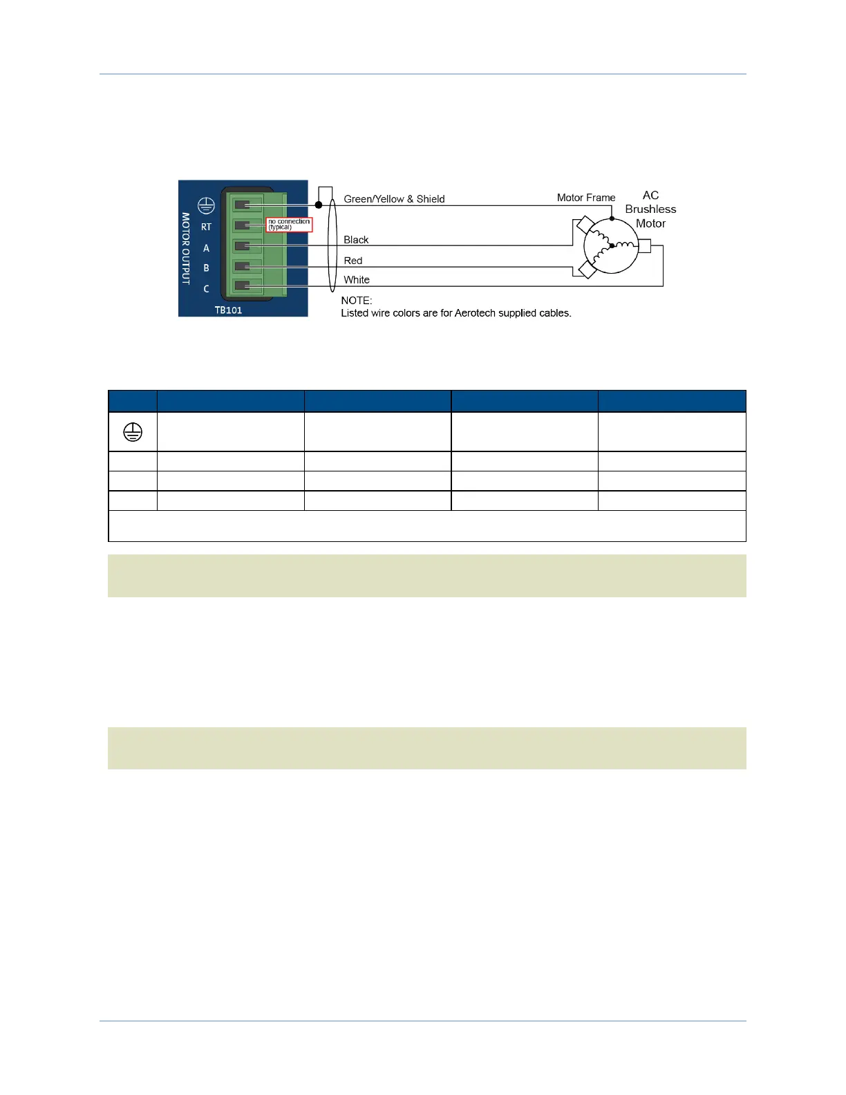
The configuration shown in Figure 2-3 is an example of a typical brushless motor connection.
Figure 2-3: Brushless Motor Configuration
Table 2-5: Wire Colors for Aerotech Supplied Cables (Brushless)
Pin
Wire Color Set 1
(1)
Wire Color Set 2 Wire Color Set 3 Wire Color Set 4
Green/Yellow &
Shield
(2)
Green/Yellow &
Shield
Green/Yellow &
Shield
Green/Yellow &
Shield
A Black Blue & Yellow Black #1 Black & Brown
B Red Red & Orange Black #2 Red & Orange
C White White & Brown Black #3 Violet & Blue
(1) Wire Color Set #1 is the typical Aerotech wire set used by Aerotech.
(2) “&” (Red & Orange) indicates two wires; “/ ” (Green/White) indicates a single wire
N O T E : Brushless motors are commutated electronically by the controller. The use of Hall effect devices
for commutation is recommended.
The controller requires that the Back-EMF of each motor phase be aligned with the corresponding Hall-effect
signal. To ensure proper alignment, motor, Hall, and encoder connections should be verified using one of the
following methods: powered, through the use of a test program; or unpowered using an oscilloscope. Both
methods will identify the A, B, and C Hall/motor lead sets and indicate the correct connections to the
controller. Refer to Section 2.2.1.1. for powered motor phasing or Section 2.2.1.2. for unpowered motor and
feedback phasing.
N O T E : If using standard Aerotech motors and cables, motor and encoder connection adjustments are
not required.
Ensemble HLe Installation and Configuration