Installation and Configuration Ensemble HLe
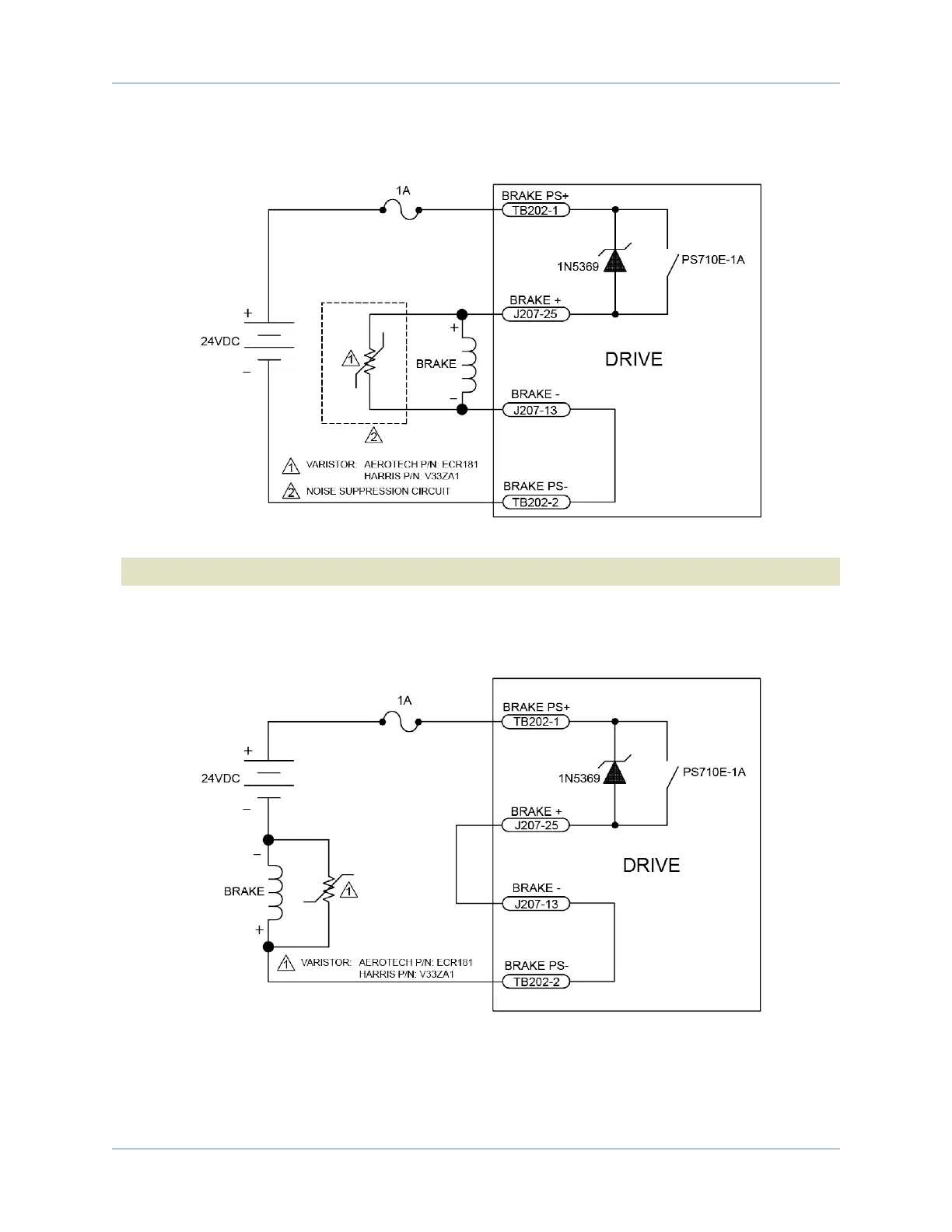
Figure 2-35 is an example of a +24 VDC brake connected to the Motor Feedback connector. In this example
the external +24 VDC power source is connected to TB202.
Figure 2-35: Brake Connected to J207
N O T E : The user is responsible for providing fuse protection for the brake circuit.
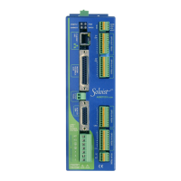
Figure 2-36 is an example of a 24 VDC brake connected to TB202. The user must connect J207 pin 13 to
J207 pin 25. In this case, J207 would function as an interlock to prevent the brake from releasing if the Motor
Feedback connector is not connected.
Figure 2-36: Brake Connected to TB202
www.aerotech.com Chapter 2 65