36 Chapter 2 www.aerotech.com
2.3.1. Encoder Interface (J207)
The Ensemble HLe is equipped with standard and auxiliary encoder feedback channels. The standard
encoder interface is accessible through the Motor Feedback (J207) connector. The standard encoder
interface will accept an RS-422 differential line driver signal. If the Ensemble HLe has been purchased with
the -MXH option, the standard encoder interface can be configured for an analog encoder input via parameter
settings.
Refer to Section 2.3.1.4. for encoder feedback phasing. Refer to Section 2.5. for the auxiliary encoder
channel.
N O T E : Encoder wiring should be physically isolated from motor, AC power, and all other power wiring.
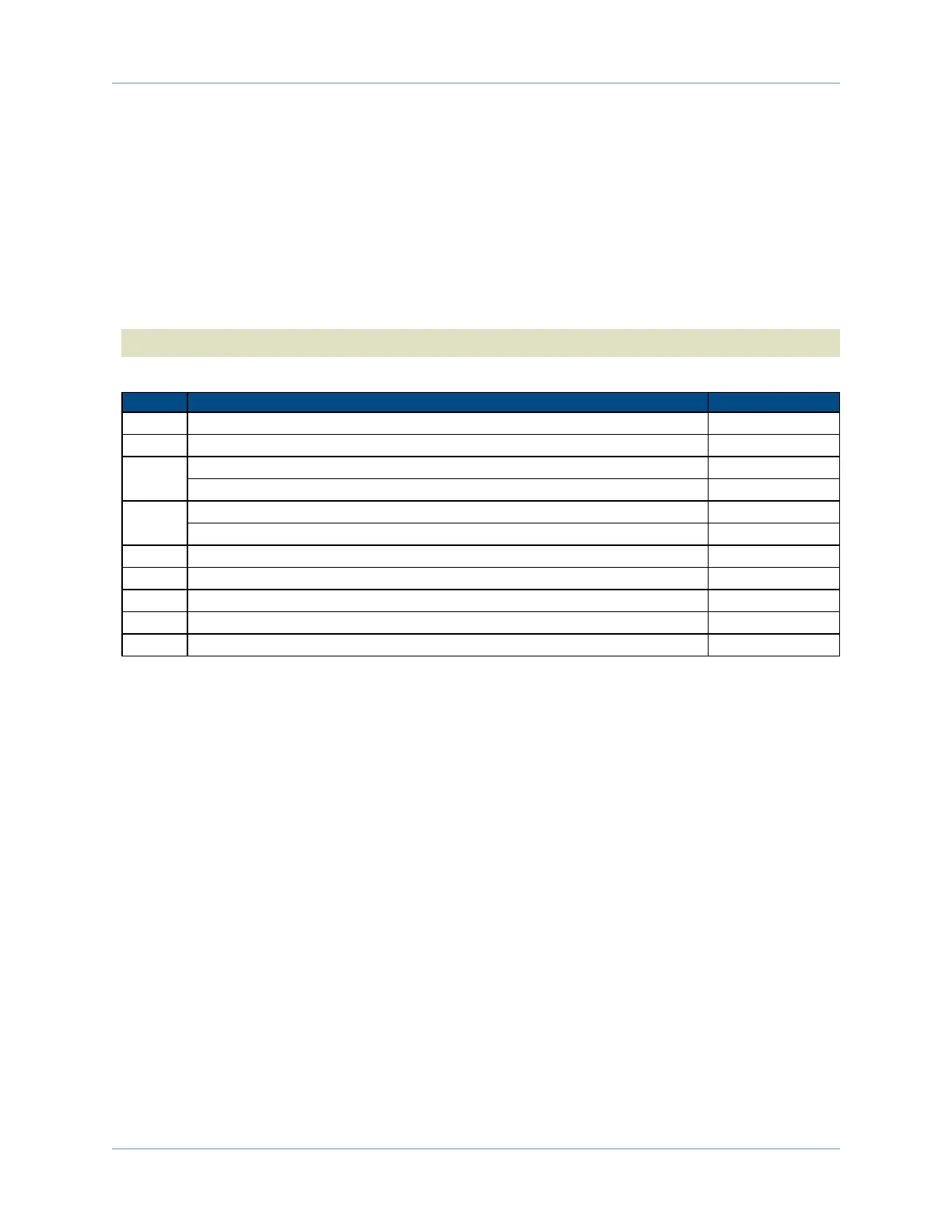
Table 2-11: Encoder Pins on the Motor Feedback Connector
Pin# Description In/Out/Bi
1 Chassis Frame Ground N/A
3 +5V Power for Encoder (500 mAmax) Output
6
Encoder Marker Reference Pulse - Input
Absolute Encoder Interface Clock - Output
7
Encoder Marker Reference Pulse + Input
Absolute Encoder Interface Clock + Output
14 Encoder Cosine + Input
15 Encoder Cosine - Input
17 Encoder Sine + Input
18 Encoder Sine - Input
21 Signal Common for Encoder N/A
Ensemble HLe Installation and Configuration