Installation and Configuration Ensemble HLe
2.3. Motor Feedback Connections (J207)
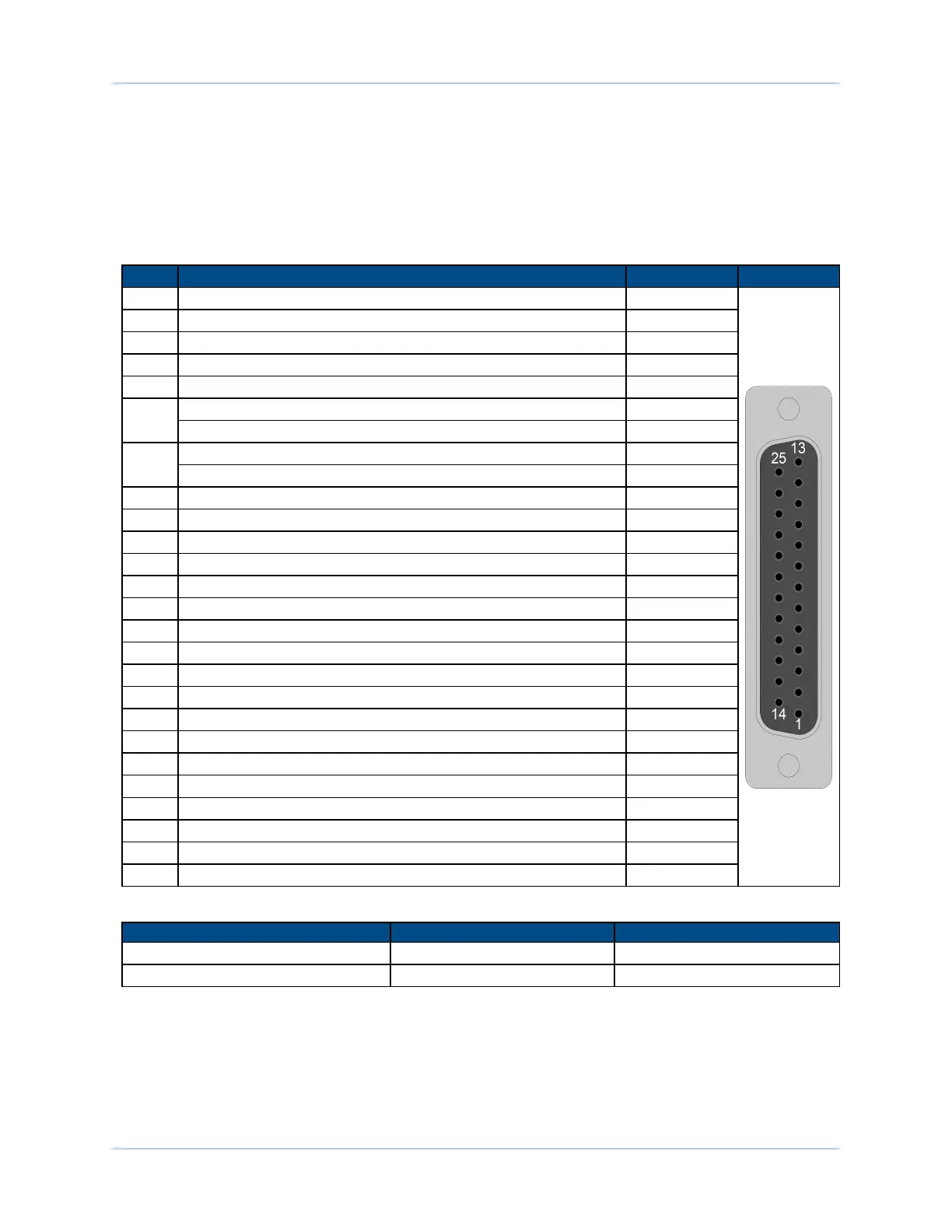
The motor feedback connector (a 25-pin, D-style connector) has inputs for an encoder, limit switches, Hall-
effect devices, motor over-temperature device, 5 Volt encoder and limit power, and optional brake
connection. The connector pin assignment is shown below with detailed connection information in the
following sections.
Table 2-9: Motor Feedback Connector Pinout (J207)
Pin# Description In/Out/Bi
Connector
1 Chassis Frame Ground N/A
2 Motor Over Temperature Thermistor Input
3 +5V Power for Encoder (500 mAmax) Output
4 Reserved N/A
5 Hall-Effect Sensor B (brushless motors only) Input
6
Encoder Marker Reference Pulse - Input
Absolute Encoder Interface Clock - Output
7
Encoder Marker Reference Pulse + Input
Absolute Encoder Interface Clock + Output
8 Absolute Encoder Interface Data - Bidirectional
9 Reserved N/A
10 Hall-Effect Sensor A (brushless motors only) Input
11 Hall-Effect Sensor C (brushless motors only) Input
12 Clockwise End of Travel Limit Input
13 Brake Output - Output
14 Encoder Cosine + Input
15 Encoder Cosine - Input
16 +5V Power for Limit Switches (500 mAmax) Output
17 Encoder Sine + Input
18 Encoder Sine - Input
19 Absolute Encoder Interface Data + Bidirectional
20 Signal Common for Limit Switches N/A
21 Signal Common for Encoder N/A
22 Home Switch Input Input
23 Encoder Fault Input Input
24 Counterclockwise End of Travel Limit Input
25 Brake Output + Output
Table 2-10: Mating Connector Part Numbers for the Motor Feedback Connector
Mating Connector Aerotech P/N Third Party P/N
25-Pin D-Connector ECK00101 FCI DB25P064TXLF
Backshell ECK00656 Amphenol 17E-1726-2
www.aerotech.com Chapter 2 35