Installation and Configuration Ensemble HLe
2.5.2. Position Synchronized Output (PSO)/Laser Firing (J205)
The PSO can be programmed to generate an output synchronized to the feedback position and is typically
used to fire a laser or sequence an external device. Trigger signals may be derived from a feedback channel
or a software trigger. The position synchronized output pulse is generated using high-speed hardware,
allowing minimal latency between the trigger condition and the output.
The PSO output is available on the dual-function AUX Marker/PSO signal lines. The auxiliary marker must
be configured as an output using the PSOOUTPUT CONTROL command. Refer to the Help File for more
information.
An opto-isolated output is available on the TB302 connector of the -IO option (see Section 3.2. for more
information).
An RS-422 line receiver or opto-isolator is recommended, especially when using long cable lengths in noisy
environments or when high frequency pulse transmission is required. It is best to locate the line receiver or
opto-isolator close to the receiving electronics.
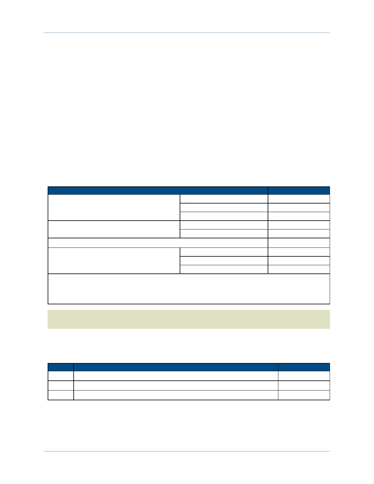
Table 2-26: PSO Specifications
Specification Value
Maximum Input Tracking Rate
(1)
Single-Axis Tracking 16.6 MHz
Dual-Axis Tracking 8.33 MHz
Triple-Axis Tracking 8.33 MHz
Maximum Quadrature Encoder Output
Frequency
Standard Feedback 40 MHz
-MXHFeedback 25 MHz
Maximum PSO Output (Fire) Frequency
(2)
12.5 MHz
Firing Latency
(3)
Single-Axis Tracking 160 nsec
Dual-Axis Tracking 220 nsec
Triple-Axis Tracking 220 nsec
1.
Signals in excess of thisrate will cause a loss of PSO accuracy.
2.
The optocoupler that you use on the output might have an effect on this rate.
3.
MXH encoder multiplier options have an additional latency of ~3.25 microseconds between the measurement position and the
update of the PSO hardware.
N O T E : When using the MRK± signals with single-ended systems, do not connect MRK+ or MRK- to
GROUND(GND).
Software controlled PSOpre-scalars may be used to limit the data rate of each encoder being tracked
without affecting the servo loop data rate.
Table 2-27: PSOOutput Pins on the Auxiliary I/O Connector (J205)
Pin# Description In/Out/Bi
19 Auxiliary Marker- / PSO output Bidirectional
20 Auxiliary Marker+ / PSO output Bidirectional
23 Analog Common -
www.aerotech.com Chapter 2 55