Installation and Configuration Ensemble HLe
2.2.3. Stepper Motor Connections
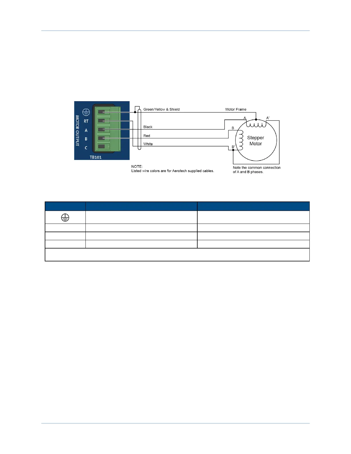
The configuration shown in Figure 2-10 is an example of a typical stepper motor connection. Refer to Section
2.2.3.1. for information on motor phasing.
In this case, the effective motor voltage is half of the applied bus voltage. For example, an 80V motor bus
supply is needed to get 40V across the motor.
Figure 2-10: Stepper Motor Configuration
Table 2-8: Wire Colors for Aerotech Supplied Cables (Stepper)
Pin
Wire Color Set 1
(1)
Wire Color Set 2
Green/Yellow & Shield
(2)
Green/Yellow & Shield
A Black Brown
B Red Yellow
C White White &Red
(1) Wire Color Set #1 is the typical Aerotech wire set used by Aerotech.
(2) “&” (Red & Orange) indicates two wires; “/ ” (Green/White) indicates a single wire
www.aerotech.com Chapter 2 33