72 Chapter 3 www.aerotech.com
N O T E : The user is responsible for providing fuse protection for the brake circuit.
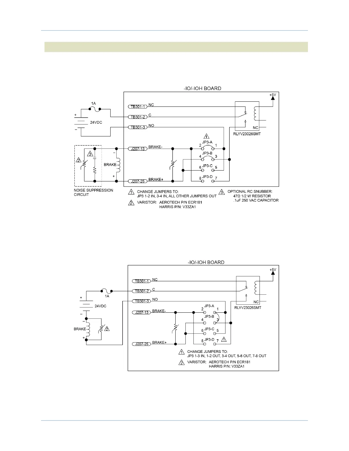
Figure 3-2 is an example of a +24 VDC Brake connected to the Motor Feedback connector. In this example
the external +24 power source is connected to TB301. Note that JP3 is set 1-2 and 3-4 with all others
removed.
Figure 3-2: Brake Connected to J207
Figure 3-3 is an example of a +24 VDC Brake connected to TB301. In this example, JP3 must be set 1-3 and
all other jumpers removed. Otherwise, the user must connect J207 pin 13 to J207 pin 25. In this case, J207
would function as an interlock to prevent the Brake from releasing if the Motor Feedback connector is not
connected.
Figure 3-3: Brake Connected to TB301
Ensemble HLe -IO Expansion Board