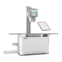
4.
Button to switch on the collimator light
5.
Front panel
6.
Vertical movement handle (both sides)
7.
Tilting extension
8.
Tilting handle
Figure 59: Radiographic wall stand, vertical version and vertical tilting
version
CAUTION:
The format indications on the front panel show the format of the
cassette or detector. Take into account that the actual area for
imaging is smaller than indicated. The image of the exposed
object is slightly magnified because there is a distance between
the front panel and the cassette or detector. The sensitive area of
the cassette or detector may be slightly smaller than the
indicated area. Check the technical data of the cassette or
detector for exact values.
Topics:
• Positioning the Radiographic Wall Stand
• Radiographic Wall Stand Accessories
156 | DR 400 | Radiographic wall stand
3231E EN 20210708 1530