11 of 26
Jun 2001
Mainframe
Agilent 6890 Gas Chromatograph Service Manual
Power/Electronics Replacement 430
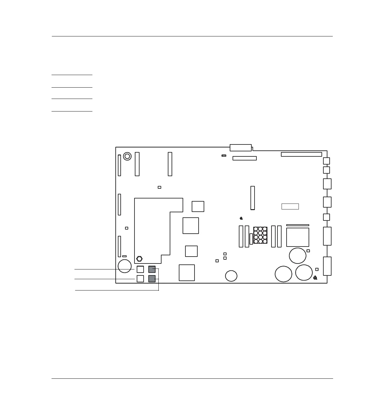
Replacing ROMs on the main board (6890A and 6890 Plus)
Replacing ROMs on the main board (6890A and 6890 Plus)
WARNING Before proceeding, turn off the main power switch and unplug the power cord.
Caution Make sure you are properly grounded with an ESD strap before continuing.
There are four ROM sockets on the lower left corner of the main board
numbered 0 to 3. Only sockets 0 and 1 (unshaded) are currently used.
Figure 430-9 Location of the ROM sockets on the main board
Removing a ROM
Insert the prongs of an AMP IC puller, part no. 8710-2303
(AMP part no. 821903-1), in the small slots in the upper left and lower right
corners of the socket and pull directly out.
Hole for
transformer
Oven Access
Cutout
Beeper
P11
P1
P2
P12
P13
P17
GND
P15
DSP
Gate
Array
CPU
GND
4 ROM
Sockets
3V
Lithium
battery
Gate
Array
P16
P21
P22
P3
J1
J2
JP1
JP2
J4
J6
J5
F2
F1
F4 F3
P18
+24V
–24V
+15V
–15V
+5v
Capacitor
Capacitors
cable
J8
ROM socket 0
ROM socket 1
ROM sockets 2 (top) and 3 (bottom)

 Loading...


