13 of 24
Jun 2001
Detectors
Agilent 6890 Gas Chromatograph Service Manual
Thermal Conductivity Detector (TCD) 330
Replacement procedures
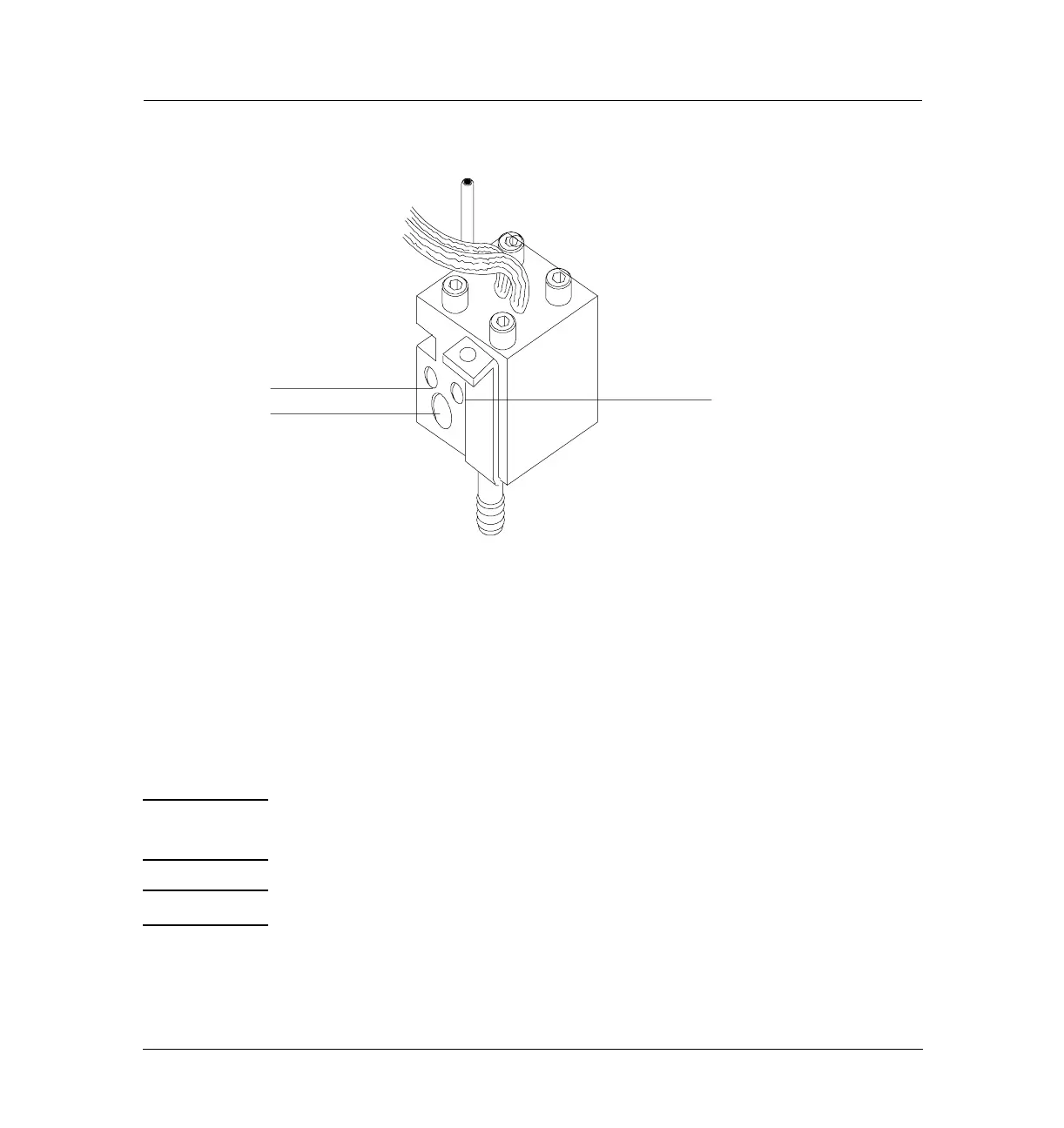
Figure 330-10 Sensor placement in the TCD cell
Removing an EPC flow manifold
Early models of the 6890 GC used Type 1 EPC flow manifolds. Later models
use Type 2 manifolds. Both types are covered here.
The TCD detector EPC flow manifold contains one inlet fitting for reference
and makeup gases. There are three tubes on the pneumatics block fitting going
to the TCD. One is the makeup gas and two are the reference gas.
WARNING Before proceeding, turn off the detector and any detector gases at their
supply. Then turn off the main power switch and unplug the power cord.
Caution Make sure you are properly grounded with an ESD strap before continuing.
1. Remove the detector cover, the pneumatics cover, metal RFI shield and
the rear top panel.
Sensor slot
Heater slot
∆PRT

 Loading...


