Chapter 4 221
Assembly Replacement
Front Frame Subassemblies
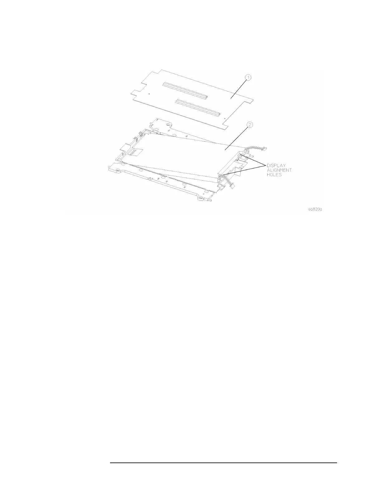
Figure 4-34 A2 Display Replacement
Display Replacement
1. Carefully slide the display into the rubber mount. Align the pins on
the mount with the holes in the display.
2. Replace the display shield.
3. Close the flaps on the rubber mount.
4. Carefully place the display mount into position in the front frame
assembly as shown in Figure 4-31.
5. Plug the flat flex cable into the display connector. Push down on both
sides of the locking mechanism.
6. Refer to Figure 4-31. Connect the backlight extension cables (5) to
the backlight connectors (6). Press the backlight extension cables
into the grooves in the rubber flaps. Make sure the white wire of the
backlight connector is on top, and the backlight cables are not
twisted.
7. Position the display flat flex cable ferrite block in the nest of the
rubber mount.

 Loading...


