30
Chapter 2: Recording on the DPS16
Overdubbing
“Overdubbing” is a recording operation in which you record another part in a new track while monitoring the
playback sound from tracks that have already been recorded. In this example, we overdub a bass guitar sound
from INPUT jack 8 to track 3 while listening to the rhythm machine recorded on tracks 1 and 2.
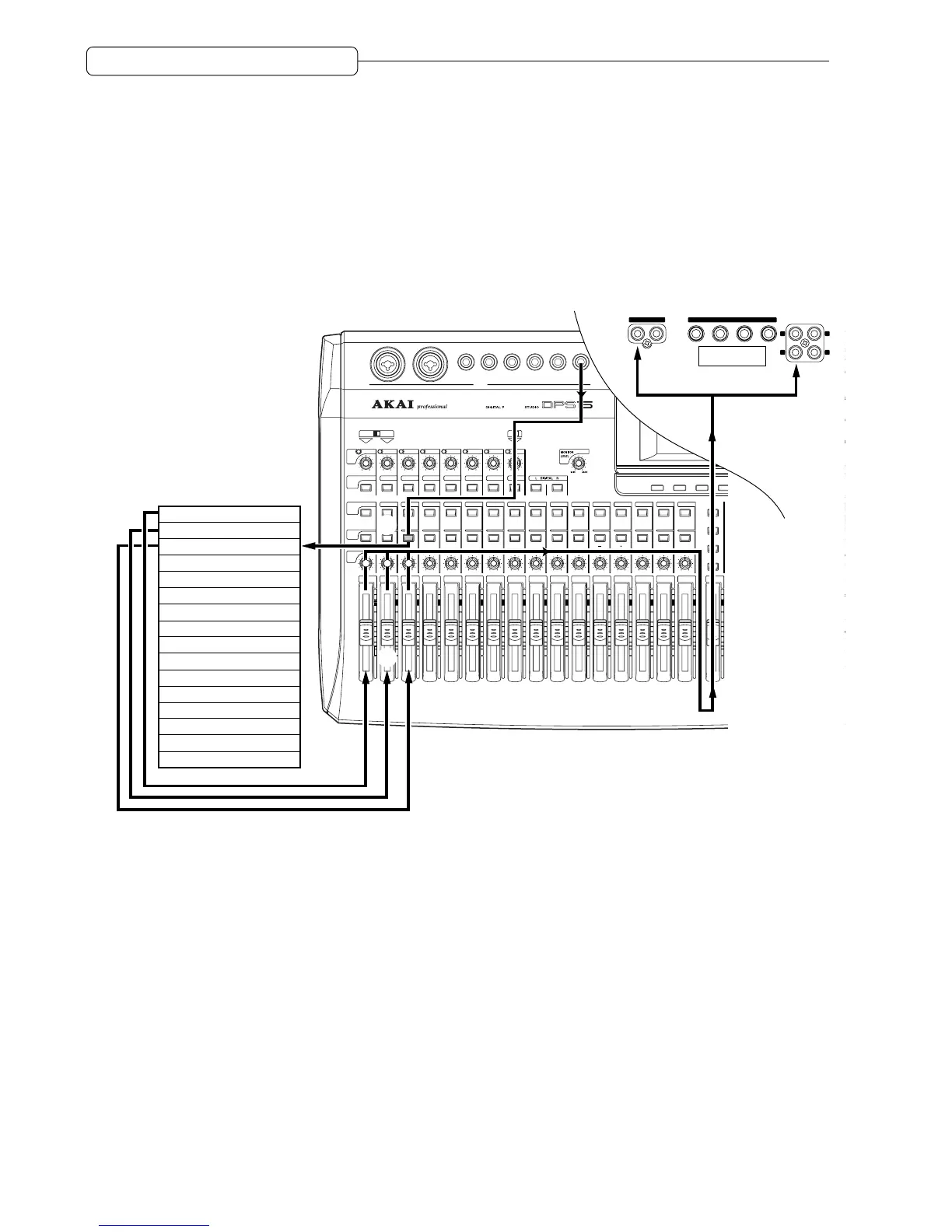
Signal flow during overdubbing
The diagram below shows a typical signal flow of overdubbing signals from INPUT 8 to track 3 while monitoring
tracks 1 and 2.
F1 F2 F3 F4 F5 F6
C1
C3
C5
C
REC
12345678
A
2
4
3
5
Track 1 (Outputs the track playback sound
j
Track 2 (Outputs the track playback sound
j
Track 3
i
Outputs the input source
j
Track 4
Track 5
Track 6
Track 7
Track 8
Track 9
Track 10
Track 11
Track 12
Track 13
Track 14
Track 15
Track 16
MASTER
OUT
MONITER
OUT
L
R
L
R
AUX SEND
1234OUT IN
DIGITAL
6
1 Change the internal routing so that the signal input at INPUT jack 8 is sent to physical track 3 of the
recorder section.
2 Press [RECORD SELECT] key 3 on the top panel to place track 3 in record-ready mode.
3 Output signals from tracks 1–3 are directed to TRACK MIX channels 1–3 of the mixer section.
4 You may adjust the level and pan settings of the TRACK MIX channel 1–3 signals using channel
faders 1–3 and [TRACK PAN] knobs 1–3 on the top panel.
5 Signals that have passed through the channel faders and the [TRACK PAN] knobs are mixed into a
stereo signal, then routed to the master section (Master bus L/R).
6 The signal adjusted by the master fader for the output level is output from the MASTER OUT jacks
and the DIGITAL OUT jack.