68 Rockwell Automation Publication 750-IN001P-EN-P - April 2017
Chapter 3 Lift and Mount the Drive
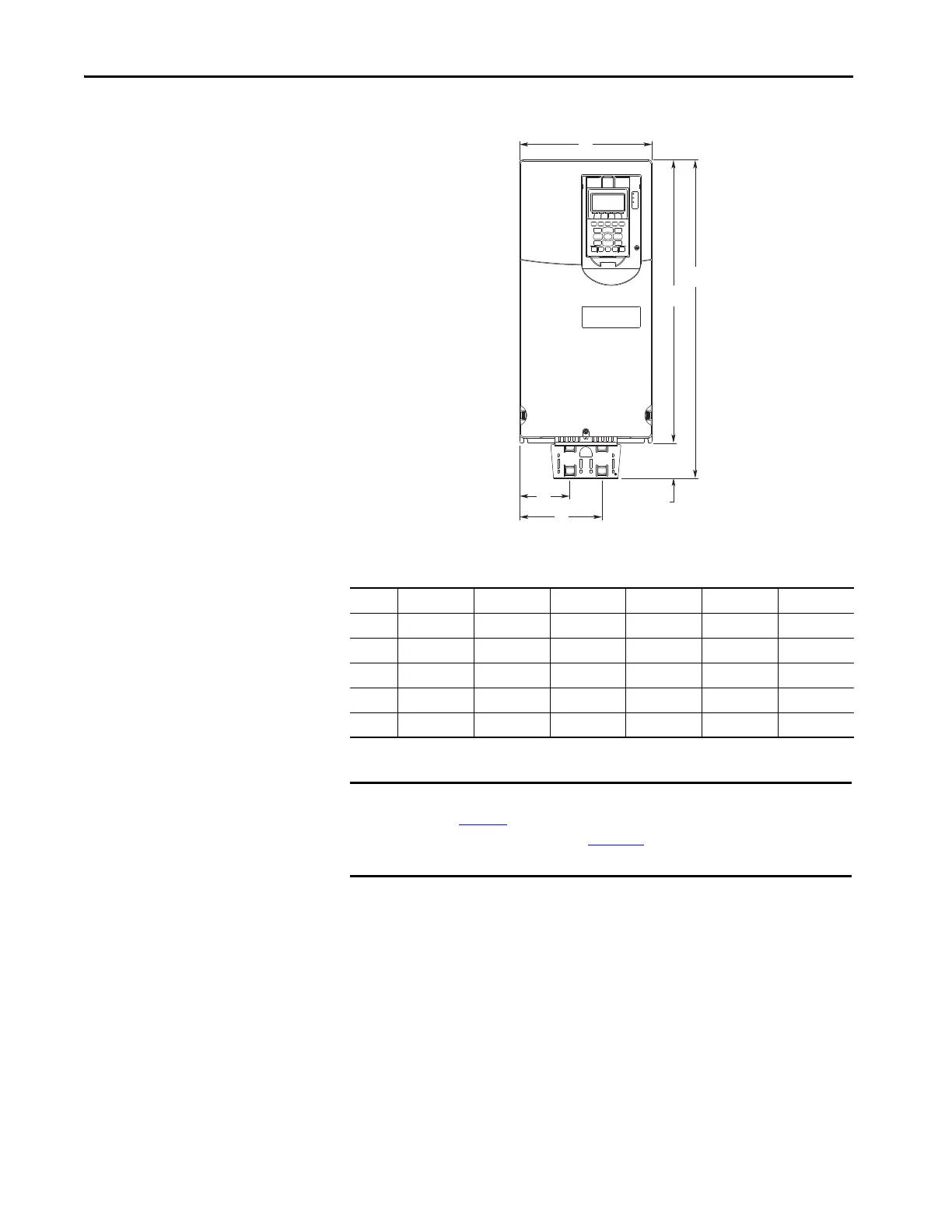
Figure 33 - EMC Plate Kit, Wall Mount Frames 1…5 (Frame 4 Shown)
Dimensions are in millimeters and (inches).
Frame A B C D E F
1 110.0 (4.33) 478.8 (18.85) 400.5 (15.77) 78.3 (3.08) 37.4 (1.47) 73.4 (2.89)
2 134.5 (5.30) 485.9 (19.13) 424.2 (16.70) 61.7 (2.43) 43.5 (1.71) 79.5 (3.13)
3 190.0 (7.48) 514.0 (20.24) 454.0 (17.87) 60.0 (2.36) 74.0 (2.91) 116.0 (4.57)
4 222.0 (8.74) 533.7 (21.01) 474.0 (18.66) 59.7 (2.35) 84.0 (3.31) 138.0 (5.43)
5 270.0 (10.63) 609.7 (24.00) 550.0 (21.65) 59.7 (2.35) 77.8 (3.06) 191.8 (7.55)
IMPORTANT EMC Kits (20-750-EMCx-Fx) do not change the mounting dimensions in
Figure 23
. See the PowerFlex® 750-Series EMC Plate and Cores Installation
Instructions, publication 750-IN006
, for detailed information on kit
installation.
 Loading...

