76 Rockwell Automation Publication 750-IN001P-EN-P - April 2017
Chapter 3 Lift and Mount the Drive
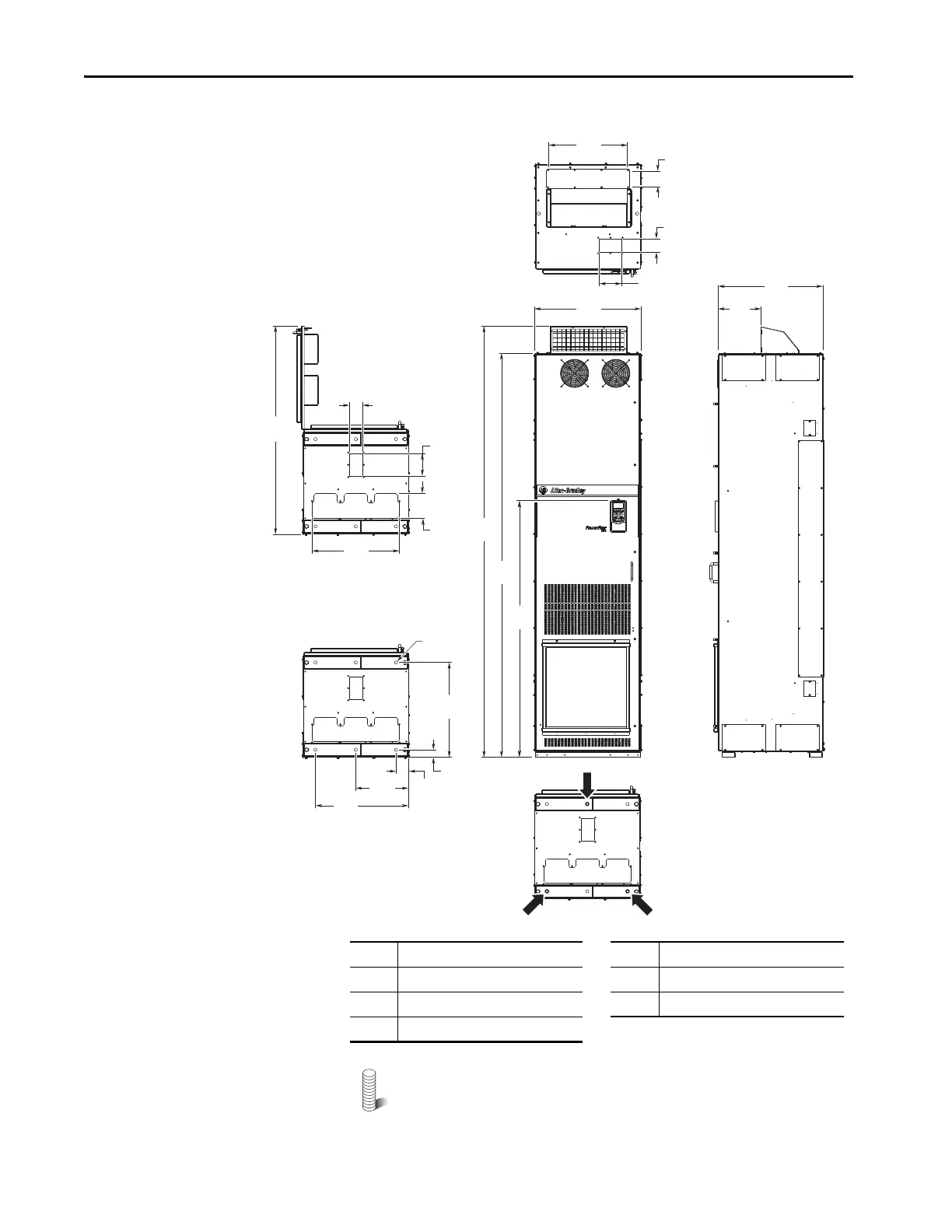
Figure 41 - IP20, NEMA/UL Type 1, MCC Style Cabinet, Floor Mount Frame 8 (Enclosure Code B)
M12 (1/2 in.) Property Class 8.8 anchor hardware is recommended
to fasten the drive cabinet through its internal mounting angle to the
foundation. Anchor bolts can be pre-located and embedded in the
foundation before instillation.
2453
(96.6)
600
(23.6)
2300
(90.6)
300
(11.8)
531
(20.9)
600
(23.6)
240
(9.4)
ø18.0
(0.71)
68
(2.7)
542
(21.3)
1183
(46.6)
141
(5.6)
43
(1.7)
69
(2.7)
127
(5.0)
76
(3.0)
76
(3.0)
1
2
2
1
3
4
5
127
(5.0)
1464
(57.6)
440
(17.3)
500
(19.7)
No. Description No. Description
1 Power wiring conduit plates. 4 Optional HIM.
2 Control wiring conduit plates. 5 Recommended three-hole anchoring.
3 Optional exhaust hood.
 Loading...

