Rockwell Automation Publication 750-UM006C-EN-P - March 2022 83
Configure and Start Up the Drive Chapter 4
• Rockwell Automation recommends that you configure the Digital
Transistor Out 0 to control the motor brake sequencing from the
drive and configure the Digital Relay Out 0 to be controlled by the
Logix controller (via Datalink), or leave it unconfigured.
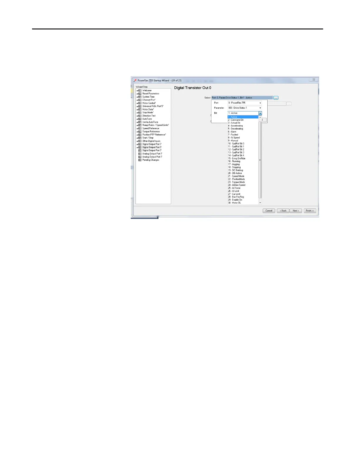
• When selecting 00:935 [Drive Status 1] bit 1 (Active) is selected in
the Digital Output step, the transistor closes anytime the drive is ON,
running with its transistors firing. The transistor opens on all other
occasions (not running, faulted, power down, and so on). The
recommended setting for Digital Transistor Out 0 is shown.
19. Click Next.
20. Click Next twice to advance to the Pending Changes step, because the
drive does not use Analog Output 1 or Analog Output 0. Click Next to
advance.

 Loading...


