Rockwell Automation Publication 750-UM006C-EN-P - March 2022 163
Drive Maintenance Chapter 5
Replace the EMC Kit (1CH030)
Follow the procedure to Remove Power on page 146 and follow the
instructions to Remove the Front Cover
on page 148. For information on how
to repair or replace the EMC kit (cat. no. 20-750-EMC1-F2) that is part of the
drive, see PowerFlex 750-Series EMC Plate and Cores - Frames 1...7,
publication 750-IN006
. After the EMC kit is replaced, follow the instructions
to Attach the Front Cover
on page 169. and to Apply Power on page 170.
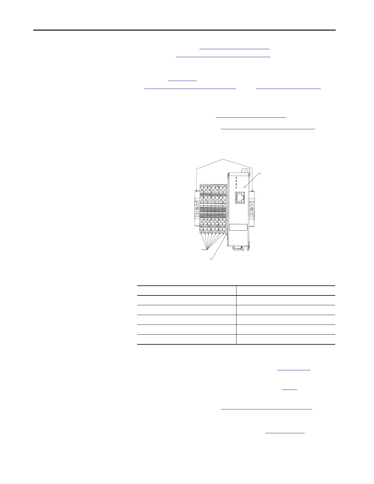
Replace the ETAP Module
(6ET210)
1. Follow the procedure to Remove Power on page 146
2. Follow the instructions to Remove the Front Cover
on page 148.
3. Use a flathead screwdriver to disconnect the wires listed in the
following table.
4. Disconnect the Ethernet cables.
5. Follow instructions in Ethernet Tap, publication 1783-PC011
to install
the new ETAP module.
6. Use a flathead screwdriver to attach the wires from step 3
to the
terminals.
7. Follow the instructions to Attach the Front Cover
on page 169.
For information on how to configure the ETAP (cat. no. 1783-ETAP), see
EtherNet/IP Network Configuration, publication ENET-UM006
.
Wire Description Terminal Number
6ET210 –0V –
6ET210 +24V +
ETH1 1 (front)
ETH2 2 (rear)
ENET_DRIVE Device port on front panel
3-port EtherNet/IP Tap
Cat. No. 1783-ETAP
IEC Terminal Block
Cat. No. 1492-LD4
IEC End Barrier
Cat. No. 1492-EBLD4
IEC End Anchor

 Loading...


