146 Rockwell Automation Publication 750-UM006C-EN-P - March 2022
Chapter 5 Drive Maintenance
Remove Power
1. Rotate the red disconnect handle counter-clockwise to the OFF
position.
2. Use a flat-head screwdriver to rotate the locks counter-clockwise to
open the auxiliary circuit breaker door on the front cover.
3. Verify that all breakers are in the OFF position.
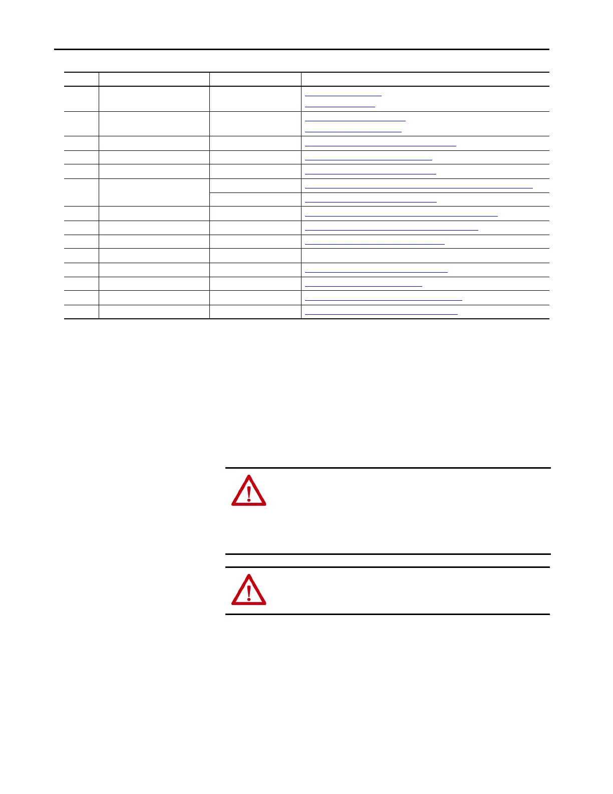
Ref. No. Component Repairable / Replaceable? Topic Covered In
Power No Remove Power
on page 146
Apply Power on page 170
Front Cover (not shown) No Remove the Front Cover on page 148
Attach the Front Cover on page 169
1Main Circuit Breaker Yes Replace the Main Circuit Breaker (1CB030) on page 153
2 Human Interface Module (HIM) Yes Replace the Drive HIM (1HIM320) on page162
3 Ethernet Tap Yes Replace the ETAP Module (6ET210) on page 163
4 Auxiliary Circuit Breakers
(1)
Yes Replace the Auxiliary Circuit Breakers (5CB070 and 1CB250 or 5CB130) on page 161
No Open Auxiliary Circuit Breaker Door on page 176
5 Surge Suppressor AC Source Brake
(2)
Yes Replace the Surge Suppressor AC Source Brake (1SUP270) on page 150
6 Surge Suppressor DC Brake
(2)
Yes Replace the DC Brake Surge Suppressor (1BD0270) on page 151
7 Brake Contactor - (upper left) Yes Replace the Brake Contactor (5BC130) on page 152
8 Common Mode Core No -
9 Receptacles (bottom) Yes Replace Receptacles on the Gland Plate on page 164
10 EMC Kit Yes Replace the EMC Kit (1CH030) on page 163
11 Drive Heatsink and Fan (behind drive) Yes Replace the PowerFlex Frame 2 Heatsink Fan on page160
12 PowerFlex® 755 Frame 2 Drive Yes Replace PowerFlex Frame 2 Drive (1EA030) on page 156
(1) The brake circuit breakers vary in design and operation based on the configurations of 24V DC mechanical brake or 400/480V AC source mechanical brake.
(2) The configuration has either AC or DC brake.
WARNING: Circumstances that can cause an explosion may exist, which may
lead to personal injury or death, property damage, or economic loss. If the
branch circuit protection device trips, you must use the software to verify
that the source brake function is still operational before putting the
equipment back in service. If the source brake function is not working
properly, loss of brake function or motor damage can occur.
ATTENTION: Do not operate controls or open covers without appropriate
personal protective equipment. Verify that all incoming power is
disconnected and discharged before removing the cover.

 Loading...


