166 Rockwell Automation Publication 750-UM006C-EN-P - March 2022
Chapter 5 Drive Maintenance
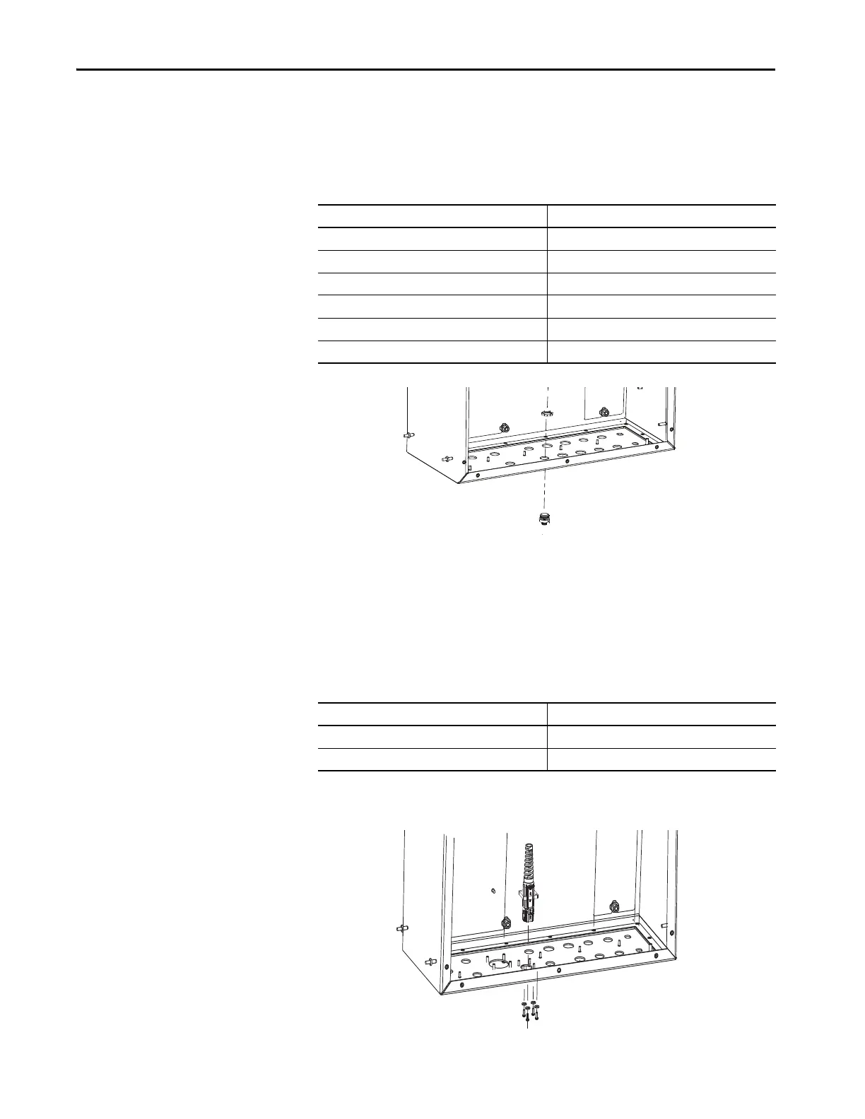
Receptacle Replacement - Type 1
The table below describes the receptacles that fall under type 1. Type 1
receptacles are installed on the bottom side of the gland plate, and the lock nut
is installed from inside the enclosure.
Receptacle Replacement - Type 2
The table below describes the receptacles that fall under type 2. Type 2
receptacles are installed with the receptacle and bulkhead adapter inside the
enclosure. The sealing washer and screws are installed from the bottom side of
the gland plate.
Receptacle Abbreviation Receptacle Function
L123 Input Power
S0 and S1 Safety
DBRT Brake Resistor Thermostat Temperature
P0 and P1 Digital Input
T123 (< 22 amp) Output Power
DBR (< 22 amp) Dynamic Brake
Receptacle Abbreviation
(1)
(2)
(1) CFBM and CPBM (for drive rating < 22 A) uses a type M4 screw.
(2) CPBM (for drive rating= 22 A) uses a type M5 screw.
Receptacle Function
CPBM Allen-Bradley Servo Motor Power and Brake
CFBM Allen-Bradley Servo Bulk Head Hiperface Encoder

 Loading...


