152 Rockwell Automation Publication 750-UM006C-EN-P - March 2022
Chapter 5 Drive Maintenance
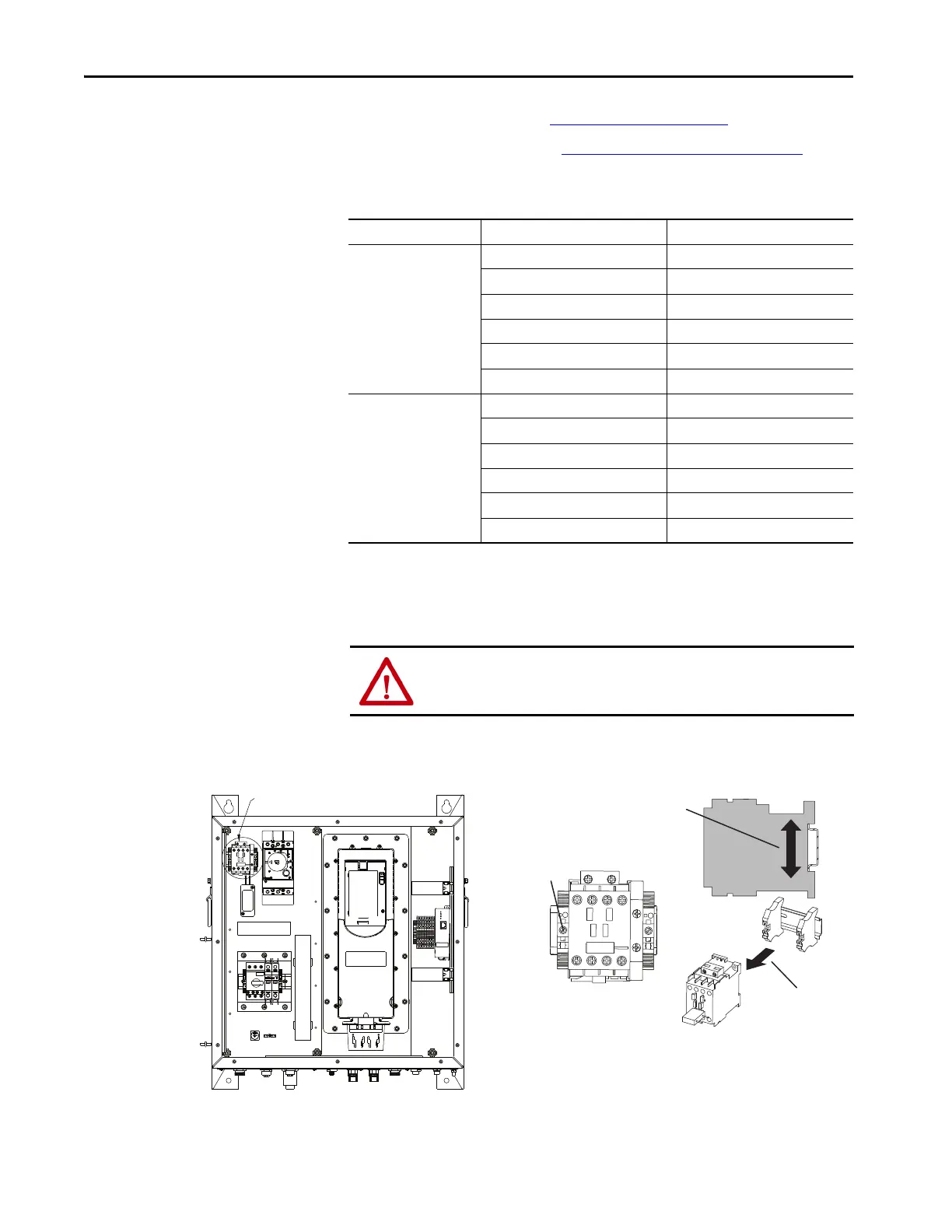
Replace the Brake Contactor
(5BC130)
1. Follow the procedure to Remove Power on page 146.
2. Follow the instructions to Remove the Front Cover
on page 148.
3. Use a flathead screwdriver to disconnect the wire from the input and
output sides of the brake contactor
4. Use flathead screwdriver to loosen the 2 screws from the end anchors
that secure the brake contactor to the enclosure.
5. Use a screwdriver to dislodge the brake contactor from the DIN rail.
6. Remove the brake contactor from the cabinet.
Location Wire Description Terminal Number
Top 5BC130-L1 L1
5BC130-L2 L2
5BC130-13 13
5BC130-A1 A1
5BC130-A2 A2
5BC130-21
(1)
(1) Only applicable to Safety option 'C'
21
Bottom 5BC130-T1 (From Connector) T1
5BC130-T1 (From Surge Suppressor) T1
5BC130-T2 (From Connector) T2
5BC130-T2 (From Surge Suppressor) T2
5BC130-14 14
5BC130-22
(1)
22
ATTENTION: Use caution when removing the service contactor from DIN rail.
Failure to use caution could result in personal injury or equipment damage.
Contactor
Cat. No.100-C09EJ10

 Loading...


