Rockwell Automation Publication 750-UM006C-EN-P - March 2022 153
Drive Maintenance Chapter 5
7. Unpack and inspect the new brake contactor.
8. Attach the brake contactor to the DIN rail.
9. Use a flathead screwdriver to tighten the two screws on the end
anchors.
Torque screws to 4.4 lb•in.
10. Use the flathead screwdriver to connect the wires/terminals to the
brake contactor according to the table in step 3
.
Torque screws to 15 lb•in.
11. Follow the instructions to Attach the Front Cover
on page 169.
Replace the Main Circuit
Breaker (1CB030)
1. Follow the procedure to Remove Power on page 146.
2. Follow the instructions to Remove the Front Cover
on page 148.
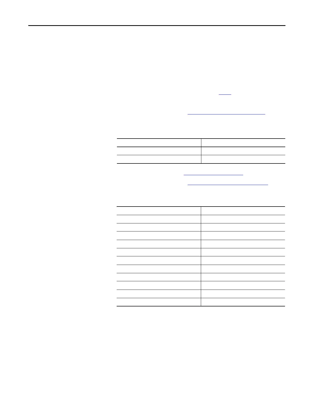
3. Use a #5 hex key to remove the wires from the input and output side of
the main circuit breaker.
Circuit Breaker Description Catalog Number
400/480V AC main power 140G-G6C3-C30-AJ
Rotary disconnect with door handle 140G-G-RVM12R
Wire Description Terminal Number
1CB030-L1 L1
1CB030-L2 L2
1CB030-L3 L3
1CB030-T1 (from 1EA030-R/L1) T1
1CB030-T1 (from 1CB250-1)
(1)
(1) Only applicable to Brake option 'SB'
T1
1CB030-T2 (from 1EA030-S/L2) T2
1CB030-T2 (from 1CB250-5)
(1)
T2
1CB030-T3 (from 1EA030-T/L3) T3
TB2-4 Connect 21 to TB2-4 Load side
1CB250-13
(1)
Connect 24 to 1CB250-13
5CB130-11
(2)
(2) Only applicable to Brake option 'B2' and 'B3'
Connect 24 to 5CB130-11

 Loading...


