Rockwell Automation Publication 750-UM006C-EN-P - March 2022 169
Drive Maintenance Chapter 5
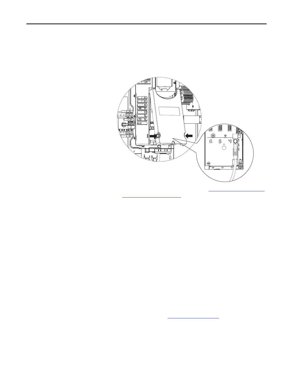
Attach the Front Cover
1. Verify that all terminals, connections, and wires are secure.
2. Verify that proper torque values were used.
3. Verify that the Ethernet cable is attached to the Frame 2 drive and the
ETAP.
4. Attach the HIM cable to the Frame 2 receptacle.
5. Attach the front covers to the Frame 2. See Replace PowerFlex Frame 2
Drive (1EA030) on page 156 for more information on attaching the
Frame 2 covers.
6. To align the drive cover, align the main circuit breaker shaft with the
rotary disconnect switch, and allow them to fully mate.
7. Rotate the cover counter-clockwise to expose the grounding stud.
8. Use a 10 mm wrench to attach the nut and washer that secure the
ground wire to the ground stud.
9. Verify that the HIM cable, ground wire, and Ethernet cable are properly
stored.
10. Rotate cover clockwise to align the cover and enclosure holes.
11. Insert the 12 M12 x 20 mm screws and washers. Use the T30 torque bit
to tighten the screws.
Torque the screws to 25 lb•in
12. Reattach connector cables to the gland plate and torque them hand-
tight.
13. Follow instructions to Apply Power
on page 170.

 Loading...


